Math Is Fun Forum
You are not logged in.
- Topics: Active | Unanswered
Pages: 1
#1 2022-02-21 20:27:40
- Jai Ganesh
- Administrator

- Registered: 2005-06-28
- Posts: 46,175
Logic gate
Logic gate
A logic gate is an idealized model of computation or a physical electronic device implementing a Boolean function, a logical operation performed on one or more binary inputs that produces a single binary output. Depending on the context, the term may refer to an ideal logic gate, one that has for instance zero rise time and unlimited fan-out, or it may refer to a non-ideal physical device.
Logic gates are primarily implemented using diodes or transistors acting as electronic switches, but can also be constructed using vacuum tubes, electromagnetic relays (relay logic), fluidic logic, pneumatic logic, optics, molecules, or even mechanical elements. With amplification, logic gates can be cascaded in the same way that Boolean functions can be composed, allowing the construction of a physical model of all of Boolean logic, and therefore, all of the algorithms and mathematics that can be described with Boolean logic.
Logic circuits include such devices as multiplexers, registers, arithmetic logic units (ALUs), and computer memory, all the way up through complete microprocessors, which may contain more than 100 million gates. In modern practice, most gates are made from MOSFETs (metal–oxide–semiconductor field-effect transistors).
Compound logic gates AND-OR-Invert (AOI) and OR-AND-Invert (OAI) are often employed in circuit design because their construction using MOSFETs is simpler and more efficient than the sum of the individual gates.
In reversible logic, Toffoli gates are used.
Toffoli gate
In logic circuits, the Toffoli gate (also CCNOT gate), invented by Tommaso Toffoli, is a universal reversible logic gate, which means that any classical reversible circuit can be constructed from Toffoli gates. It is also known as the "controlled-controlled-not" gate, which describes its action. It has 3-bit inputs and outputs; if the first two bits are both set to 1, it inverts the third bit, otherwise all bits stay the same.
Electronic gates
A functionally complete logic system may be composed of relays, valves (vacuum tubes), or transistors. The simplest family of logic gates uses bipolar transistors, and is called resistor–transistor logic (RTL). Unlike simple diode logic gates (which do not have a gain element), RTL gates can be cascaded indefinitely to produce more complex logic functions. RTL gates were used in early integrated circuits. For higher speed and better density, the resistors used in RTL were replaced by diodes resulting in diode–transistor logic (DTL). Transistor–transistor logic (TTL) then supplanted DTL. As integrated circuits became more complex, bipolar transistors were replaced with smaller field-effect transistors (MOSFETs); see PMOS and NMOS. To reduce power consumption still further, most contemporary chip implementations of digital systems now use CMOS logic. CMOS uses complementary (both n-channel and p-channel) MOSFET devices to achieve a high speed with low power dissipation.
For small-scale logic, designers now use prefabricated logic gates from families of devices such as the TTL 7400 series by Texas Instruments, the CMOS 4000 series by RCA, and their more recent descendants. Increasingly, these fixed-function logic gates are being replaced by programmable logic devices, which allow designers to pack many mixed logic gates into a single integrated circuit. The field-programmable nature of programmable logic devices such as FPGAs has reduced the 'hard' property of hardware; it is now possible to change the logic design of a hardware system by reprogramming some of its components, thus allowing the features or function of a hardware implementation of a logic system to be changed.
Electronic logic gates differ significantly from their relay-and-switch equivalents. They are much faster, consume much less power, and are much smaller (all by a factor of a million or more in most cases). Also, there is a fundamental structural difference. The switch circuit creates a continuous metallic path for current to flow (in either direction) between its input and its output. The semiconductor logic gate, on the other hand, acts as a high-gain voltage amplifier, which sinks a tiny current at its input and produces a low-impedance voltage at its output. It is not possible for current to flow between the output and the input of a semiconductor logic gate.
Another important advantage of standardized integrated circuit logic families, such as the 7400 and 4000 families, is that they can be cascaded. This means that the output of one gate can be wired to the inputs of one or several other gates, and so on. Systems with varying degrees of complexity can be built without great concern of the designer for the internal workings of the gates, provided the limitations of each integrated circuit are considered.
The output of one gate can only drive a finite number of inputs to other gates, a number called the 'fan-out limit'. Also, there is always a delay, called the 'propagation delay', from a change in input of a gate to the corresponding change in its output. When gates are cascaded, the total propagation delay is approximately the sum of the individual delays, an effect which can become a problem in high-speed circuits. Additional delay can be caused when many inputs are connected to an output, due to the distributed capacitance of all the inputs and wiring and the finite amount of current that each output can provide.
History and development
The binary number system was refined by Gottfried Wilhelm Leibniz (published in 1705), influenced by the ancient I Ching's binary system. Leibniz established that using the binary system combined the principles of arithmetic and logic.
In an 1886 letter, Charles Sanders Peirce described how logical operations could be carried out by electrical switching circuits. Eventually, vacuum tubes replaced relays for logic operations. Lee De Forest's modification, in 1907, of the Fleming valve can be used as a logic gate. Ludwig Wittgenstein introduced a version of the 16-row truth table as proposition 5.101 of Tractatus Logico-Philosophicus (1921). Walther Bothe, inventor of the coincidence circuit, got part of the 1954 Nobel Prize in physics, for the first modern electronic AND gate in 1924. Konrad Zuse designed and built electromechanical logic gates for his computer Z1 (from 1935 to 1938).
From 1934 to 1936, NEC engineer Akira Nakashima, Claude Shannon and Viktor Shetakov introduced switching circuit theory in a series of papers showing that two-valued Boolean algebra, which they discovered independently, can describe the operation of switching circuits. Using this property of electrical switches to implement logic is the fundamental concept that underlies all electronic digital computers. Switching circuit theory became the foundation of digital circuit design, as it became widely known in the electrical engineering community during and after World War II, with theoretical rigor superseding the ad hoc methods that had prevailed previously.
Metal-oxide-semiconductor (MOS) devices in the forms of PMOS and NMOS were demonstrated by Bell Labs engineers Mohamed M. Atalla and Dawon Kahng in 1960. Both types were later combined and adapted into complementary MOS (CMOS) logic by Chih-Tang Sah and Frank Wanlass at Fairchild Semiconductor in 1963.
Active research is taking place in molecular logic gates.
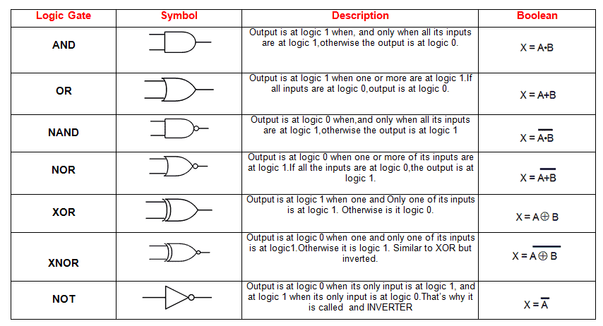
Symbols
There are two sets of symbols for elementary logic gates in common use, both defined in ANSI/IEEE Std 91-1984 and its supplement ANSI/IEEE Std 91a-1991. The "distinctive shape" set, based on traditional schematics, is used for simple drawings and derives from United States Military Standard MIL-STD-806 of the 1950s and 1960s. It is sometimes unofficially described as "military", reflecting its origin. The "rectangular shape" set, based on ANSI Y32.14 and other early industry standards as later refined by IEEE and IEC, has rectangular outlines for all types of gate and allows representation of a much wider range of devices than is possible with the traditional symbols. The IEC standard, IEC 60617-12, has been adopted by other standards, such as EN 60617-12:1999 in Europe, BS EN 60617-12:1999 in the United Kingdom, and DIN EN 60617-12:1998 in Germany.
The mutual goal of IEEE Std 91-1984 and IEC 60617-12 was to provide a uniform method of describing the complex logic functions of digital circuits with schematic symbols. These functions were more complex than simple AND and OR gates. They could be medium scale circuits such as a 4-bit counter to a large scale circuit such as a microprocessor.
IEC 617-12 and its successor IEC 60617-12 do not explicitly show the "distinctive shape" symbols, but do not prohibit them. These are, however, shown in ANSI/IEEE 91 (and 91a) with this note: "The distinctive-shape symbol is, according to IEC Publication 617, Part 12, not preferred, but is not considered to be in contradiction to that standard." IEC 60617-12 correspondingly contains the note (Section 2.1) "Although non-preferred, the use of other symbols recognized by official national standards, that is distinctive shapes in place of symbols, shall not be considered to be in contradiction with this standard. Usage of these other symbols in combination to form complex symbols (for example, use as embedded symbols) is discouraged." This compromise was reached between the respective IEEE and IEC working groups to permit the IEEE and IEC standards to be in mutual compliance with one another.
In the 1980s, schematics were the predominant method to design both circuit boards and custom ICs known as gate arrays. Today custom ICs and the field-programmable gate array are typically designed with Hardware Description Languages (HDL) such as Verilog or VHDL.
It appears to me that if one wants to make progress in mathematics, one should study the masters and not the pupils. - Niels Henrik Abel.
Nothing is better than reading and gaining more and more knowledge - Stephen William Hawking.
Offline
Pages: 1