Math Is Fun Forum
You are not logged in.
- Topics: Active | Unanswered
Pages: 1
#1 2026-03-20 17:25:02
- Jai Ganesh
- Administrator

- Registered: 2005-06-28
- Posts: 53,831
Airplane
Airplane
Gist
"Airplane" and "aeroplane" are the same thing—a powered, fixed-wing aircraft—but differ by regional usage. "Airplane" is standard in American English, while "aeroplane" is preferred in British and Commonwealth English. Both terms originated from the French aéroplane, with the U.S. adopting "airplane" after the Wright brothers' flight.
According to the Oxford English Dictionary, "Airplane became the standard U.S. term (replacing aeroplane) after it was adopted by the National Advisory Committee for Aeronautics in 1916."
Summary
An airplane (American English), or aeroplane (Commonwealth English), informally plane, is a fixed-wing aircraft that is propelled forward by thrust from a jet engine, propeller, or rocket engine. Airplanes come in a variety of sizes, shapes, and wing configurations. The broad spectrum of uses for airplanes includes recreation, transportation of goods and people, military, and research.
Worldwide, commercial aviation transports more than four billion passengers annually on airliners and transports more than 200 billion tonne-kilometers of cargo annually, which is less than 1% of the world's cargo movement. Most airplanes are flown by a pilot on board the aircraft, but some are designed to be remotely or computer-controlled, such as drones.
The Wright brothers invented and flew the first airplane in 1903, recognized as "the first sustained and controlled heavier-than-air powered flight". They built on the works of George Cayley, dating from 1799, when he set forth the concept of the modern airplane (and later built and flew models and successful passenger-carrying gliders) and the work of German pioneer of human aviation Otto Lilienthal, who, between 1867 and 1896, also studied heavier-than-air flight. Lilienthal's flight attempts in 1891 are seen as the beginning of human flight. Following its limited use in World War I, aircraft technology continued to develop. Airplanes had a presence in all the major battles of World War II.
The first jet aircraft was the German Heinkel He 178 in 1939. The first jet airliner, the de Havilland Comet, was introduced in 1952. The Boeing 707, the first widely successful commercial jet, was in commercial service for more than 60 years, from 1958 to 2019.
Details
An airplane is any of a class of fixed-wing aircraft that is heavier than air, propelled by a screw propeller or a high-velocity jet, and supported by the dynamic reaction of the air against its wings. For an account of the development of the airplane and the advent of civil aviation see history of flight.
The essential components of an airplane are a wing system to sustain it in flight, tail surfaces to stabilize the wings, movable surfaces to control the attitude of the plane in flight, and a power plant to provide the thrust necessary to push the vehicle through the air. Provision must be made to support the plane when it is at rest on the ground and during takeoff and landing. Most planes feature an enclosed body (fuselage) to house the crew, passengers, and cargo; the math is the area from which the pilot operates the controls and instruments to fly the plane.
Principles of aircraft flight and operation:
Aerodynamics
An aircraft in straight-and-level unaccelerated flight has four forces acting on it. (In turning, diving, or climbing flight, additional forces come into play.) These forces are lift, an upward-acting force; drag, a retarding force of the resistance to lift and to the friction of the aircraft moving through the air; weight, the downward effect that gravity has on the aircraft; and thrust, the forward-acting force provided by the propulsion system (or, in the case of unpowered aircraft, by using gravity to translate altitude into speed). Drag and weight are elements inherent in any object, including an aircraft. Lift and thrust are artificially created elements devised to enable an aircraft to fly.
Understanding lift first requires an understanding of an airfoil, which is a structure designed to obtain reaction upon its surface from the air through which it moves. Early airfoils typically had little more than a slightly curved upper surface and a flat undersurface. Over the years, airfoils have been adapted to meet changing needs. By the 1920s, airfoils typically had a rounded upper surface, with the greatest height being reached in the first third of the chord (width). In time, both upper and lower surfaces were curved to a greater or lesser degree, and the thickest part of the airfoil gradually moved backward. As airspeeds grew, there was a requirement for a very smooth passage of air over the surface, which was achieved in the laminar-flow airfoil, where the camber was farther back than contemporary practice dictated. Supersonic aircraft required even more drastic changes in airfoil shapes, some losing the roundness formerly associated with a wing and having a double-wedge shape.
By moving forward in the air, the wing’s airfoil obtains a reaction useful for flight from the air passing over its surface. (In flight the airfoil of the wing normally produces the greatest amount of lift, but propellers, tail surfaces, and the fuselage also function as airfoils and generate varying amounts of lift.) In the 18th century the Swiss mathematician Daniel Bernoulli discovered that, if the velocity of air is increased over a certain point of an airfoil, the pressure of the air is decreased. Air flowing over the curved top surface of the wing’s airfoil moves faster than the air flowing on the bottom surface, decreasing the pressure on top. The higher pressure from below pushes (lifts) the wing up to the lower pressure area. Simultaneously the air flowing along the underside of the wing is deflected downward, providing a Newtonian equal and opposite reaction and contributing to the total lift.
The lift an airfoil generates is also affected by its “angle of attack”—i.e., its angle relative to the wind. Both lift and angle of attack can be immediately, if crudely, demonstrated, by holding one’s hand out the window of a moving automobile. When the hand is turned flat to the wind, much resistance is felt and little “lift” is generated, for there is a turbulent region behind the hand. The ratio of lift to drag is low. When the hand is held parallel to the wind, there is far less drag and a moderate amount of lift is generated, the turbulence smooths out, and there is a better ratio of lift to drag. However, if the hand is turned slightly so that its forward edge is raised to a higher angle of attack, the generation of lift will increase. This favourable increase in the lift-to-drag ratio will create a tendency for the hand to “fly” up and over. The greater the speed, the greater the lift and drag will be. Thus, total lift is related to the shape of the airfoil, the angle of attack, and the speed with which the wing passes through the air.
Weight is a force that acts opposite to lift. Designers thus attempt to make the aircraft as light as possible. Because all aircraft designs have a tendency to increase in weight during the development process, modern aerospace engineering staffs have specialists in the field controlling weight from the beginning of the design. In addition, pilots must control the total weight that an aircraft is permitted to carry (in passengers, fuel, and freight) both in amount and in location. The distribution of weight (i.e., the control of the centre of gravity of the aircraft) is as important aerodynamically as the amount of weight being carried.
Thrust, the forward-acting force, is opposed to drag as lift is opposed to weight. Thrust is obtained by accelerating a mass of ambient air to a velocity greater than the speed of the aircraft; the equal and opposite reaction is for the aircraft to move forward. In reciprocating or turboprop-powered aircraft, thrust derives from the propulsive force caused by the rotation of the propeller, with residual thrust provided by the exhaust. In a jet engine, thrust derives from the propulsive force of the rotating blades of a turbine compressing air, which is then expanded by the combustion of introduced fuel and exhausted from the engine. In a rocket-powered aircraft, the thrust is derived from the equal and opposite reaction to the burning of the rocket propellant. In a sailplane, height attained by mechanical, orographic, or thermal techniques is translated into speed by means of gravity.
Acting in continual opposition to thrust is drag, which has two elements. Parasitic drag is that caused by form resistance (due to shape), skin friction, interference, and all other elements that are not contributing to lift; induced drag is that created as a result of the generation of lift.
Parasitic drag rises as airspeed increases. For most flights it is desirable to have all drag reduced to a minimum, and for this reason considerable attention is given to streamlining the form of the aircraft by eliminating as much drag-inducing structure as possible (e.g., enclosing the math with a canopy, retracting the landing gear, using flush riveting, and painting and polishing surfaces). Some less obvious elements of drag include the relative disposition and area of fuselage and wing, engine, and empennage surfaces; the intersection of wings and tail surfaces; the unintentional leakage of air through the structure; the use of excess air for cooling; and the use of individual shapes that cause local airflow separation.
Induced drag is caused by that element of the air deflected downward which is not vertical to the flight path but is tilted slightly rearward from it. As the angle of attack increases, so does drag; at a critical point, the angle of attack can become so great that the airflow is broken over the upper surface of the wing, and lift is lost while drag increases. This critical condition is termed the stall.
Lift, drag, and stall are all variously affected by the shape of the wing planform. An elliptical wing like that used on the Supermarine Spitfire fighter of World War II, for example, while ideal aerodynamically in a subsonic aircraft, has a more undesirable stall pattern than a simple rectangular wing.
The aerodynamics of supersonic flight are complex. Air is compressible, and, as speeds and altitudes increase, the speed of the air flowing over the aircraft begins to exceed the speed of the aircraft through the air. The speed at which this compressibility affects an aircraft is expressed as a ratio of the speed of the aircraft to the speed of sound, called the Mach number, in honour of the Austrian physicist Ernst Mach. The critical Mach number for an aircraft has been defined as that at which on some point of the aircraft the airflow has reached the speed of sound.
At Mach numbers in excess of the critical Mach number (that is, speeds at which the airflow exceeds the speed of sound at local points on the airframe), there are significant changes in forces, pressures, and moments acting on the wing and fuselage caused by the formation of shock waves. One of the most important effects is a very large increase in drag as well as a reduction in lift. Initially designers sought to reach higher critical Mach numbers by designing aircraft with very thin airfoil sections for the wing and horizontal surfaces and by ensuring that the fineness ratio (length to diameter) of the fuselage was as high as possible. Wing thickness ratios (the thickness of the wing divided by its width) were about 14 to 18 percent on typical aircraft of the 1940–45 period; in later jets the ratio was reduced to less than 5 percent. These techniques delayed the local airflow reaching Mach 1.0, permitting slightly higher critical Mach numbers for the aircraft. Independent studies in Germany and the United States showed that reaching the critical Mach could be delayed further by sweeping the wings back. Wing sweep was extremely important to the development of the German World War II Messerschmitt Me 262, the first operational jet fighter, and to postwar fighters such as the North American F-86 Sabre and the Soviet MiG-15. These fighters operated at high subsonic speeds, but the competitive pressures of development required aircraft that could operate at transonic and supersonic speeds. The power of jet engines with afterburners made these speeds technically possible, but designers were still handicapped by the huge rise in drag in the transonic area. The solution involved adding volume to the fuselage ahead of and behind the wing and reducing it near the wing and tail, to create a cross-sectional area that more nearly approximated the ideal area to limit transonic drag. Early applications of this rule resulted in a “wasp-waist” appearance, such as that of the Convair F-102. In later jets application of this rule is not as apparent in the aircraft’s planform.
Devices for aerodynamic control
In some flight conditions—descent, preparing to land, landing, and after landing—it is desirable to be able to increase drag to decelerate the aircraft. A number of devices have been designed to accomplish this. These include speed brakes, which are large flat-plate areas that can be deployed by the pilot to increase drag dramatically and are most often found on military aircraft, and spoilers, which are surfaces that can be extended on the wing or fuselage to disrupt the air flow and create drag or to act in the same manner as ailerons. Drag can also be provided by extension of the landing gear or, at the appropriate airspeeds, deployment of the flaps and other lift devices. Lift and drag are roughly proportional to the wing area of an aircraft; if all other factors remain the same and the wing area is doubled, both lift and drag will be doubled. Designers therefore attempt to minimize drag by keeping the wing area as small as possible, while enhancing lift with certain types of trailing-edge flaps and leading-edge slats, which have the ability to increase wing area mechanically. (These devices also alter the camber of the wing, increasing both lift and drag.) A passenger in an aft window seat of a modern airliner can observe the remarkable way in which the wing quite literally transforms itself from a smooth, slim, streamlined surface into almost a half-circle of surfaces by the deployment of a formidable array of lift- and drag-inducing devices.
Flaps are extensions of the trailing edge of the wing and can be deflected downward as much as 45°. Many flaps effectively increase wing area, adding to lift and to drag. The angle to which the flaps are deployed determines the relative amount of additional lift or drag obtained. At smaller angles, lift is typically increased over drag, while at greater angles, drag is dramatically increased over lift. Flaps come in a wide variety of types, including the simple split flap, in which a hinged section of the undersurface of the trailing edge of the wing can be extended; the Fowler flap, which extends the wing area by deploying on tracks, creating a slotted effect; and the Kreuger flap, which is a leading-edge flap often used in combination with Fowler or other trailing-edge flaps.
Various modern proprietary systems of multiple slotted flaps are used in conjunction with leading-edge slats and flaps, all specially designed to suit the flight characteristics of the particular airplane. Leading-edge flaps alter the camber of the wing and provide additional lift; leading-edge slats are small cambered airfoil surfaces arranged near the leading edge of the wing to form a slot. Air flows through the slot and over the main wing, smoothing out the airflow over the wing and delaying the onset of the stall. Leading-edge slots, which can be either fixed or deployable, are spanwise apertures that permit air to flow through a point behind the leading edge and, like the slat, are designed to smooth out the airflow over the wing at higher angles of attack.
The deployment of these devices can be varied to suit the desired flight regime. For takeoff and in the approach to landing, their deployment is generally to provide greater lift than drag. In flight or after touchdown, if rapid deceleration is desired, they can be deployed in a manner to greatly increase drag.
Primary flight controls
All four forces—lift, thrust, drag, and weight—interact continuously in flight and are in turn affected by such things as the torque effect of the propeller, centrifugal force in turns, and other elements, but all are made subject to the pilot by means of the controls.
Elevator, aileron, and rudder controls
The pilot controls the forces of flight and the aircraft’s direction and attitude by means of flight controls. Conventional flight controls consist of a stick or wheel control column and rudder pedals, which control the movement of the elevator and ailerons and the rudder, respectively, through a system of cables or rods. In very sophisticated modern aircraft, there is no direct mechanical linkage between the pilot’s controls and the control surfaces; instead they are actuated by electric motors. The catch phrase for this arrangement is “fly-by-wire.” In addition, in some large and fast aircraft, controls are boosted by hydraulically or electrically actuated systems. In both the fly-by-wire and boosted controls, the feel of the control reaction is fed back to the pilot by simulated means.
In the conventional arrangement the elevator, attached to the horizontal stabilizer, controls movement around the lateral axis and in effect controls the angle of attack. Forward movement of the control column lowers the elevator, depressing the nose and raising the tail; backward pressure raises the elevator, raising the nose and lowering the tail. Many modern aircraft combine the elevator and stabilizer into a single control surface called the stabilator, which moves as an entity to control inputs.
The ailerons are movable surfaces hinged to the trailing edge of each wing, which move in the opposite direction to control movement around the aircraft’s longitudinal axis. If the pilot applies left pressure to the control column (stick or wheel), the right aileron deflects downward and the left aileron deflects upward. The force of the airflow is altered by these control changes, causing the left wing to lower (because of decreased lift) and the right wing to rise (because of increased lift). This differential in lift causes the aircraft to turn to the left.
The rudder is a vertical surface, and it controls movement around the aircraft’s vertical axis. It does not cause the aircraft to turn; instead, it counteracts the adverse yaw (rotation around the vertical axis) produced by the ailerons. The lowered wing has both decreased lift and decreased drag; the raised wing has both increased lift and increased drag. The added drag of the raised wing tries to pull the nose of the aircraft toward it (i.e., away from the direction of the turn). Pressure on the rudder is used to counter this adverse yaw. Because the turn results in a net decrease in lift, application of elevator pressure is necessary. Thus, a turn is the result of the combined inputs of the ailerons, rudder, and elevator.
Trim tabs are used by the pilot to relieve the requirement of maintaining continuous pressure on the controls. These are smaller surfaces inset into the rudder, elevator, and ailerons, which can be positioned by mechanical or electrical means and which, when positioned, move the control surface to the desired trimmed position. Trimming the aircraft is a continual process, with adjustments necessary for changes to the flight or power controls that result in changes in speed or attitude.
Thrust controls
The pilot controls thrust by adjustment of the control levers for the engine. In an aircraft with a reciprocating engine these can consist of a throttle, mixture control (to control the ratio of fuel and air going to the engine), and propeller control as well as secondary devices such as supercharger controls or water-alcohol injection. In a turbojet engine, the principal control is the throttle, with auxiliary devices such as water injection and afterburners. With water injection, a water-alcohol mixture is injected into the combustion area to cool it, which allows more fuel to be burned. With afterburners, fuel is injected behind the combustion section and ignited to increase thrust greatly at the expense of high fuel consumption. The power delivered by reciprocating and jet engines is variously affected by airspeed and ambient air density (temperature, humidity, and pressure), which must be taken into consideration when establishing power settings. In a turboprop engine, power is typically set by first adjusting the propeller speed with a propeller lever and then adjusting fuel flow to obtain the desired torque (power) setting with the power lever.
Propellers
Propellers are basically rotating airfoils, and they vary in type, including two-blade fixed pitch, four-blade controllable (variable) pitch, and eight-blade contrarotating pitch. The blade angle on fixed-pitch propellers is set for only one flight regime, and this restriction limits their performance. Some fixed-pitch propellers can be adjusted on the ground to improve performance in one part of the flight regime. Variable-pitch propellers permit the pilot to adjust the pitch to suit the flight condition, using a low pitch for takeoff and a high pitch for cruising flight. Most modern aircraft have an automatic variable-pitch propeller, which can be set to operate continuously in the most efficient mode for the flight regime. If an engine fails, most modern propellers can be feathered (mechanically adjusted) so that they present the blade edgewise to the line of flight, thereby reducing drag. In large piston engine aircraft, some propellers can be reversed after landing to shorten the landing run. (Jet engines have thrust reversers, usually incorporating a noise-suppression system, to accomplish the same task.)
Instrumentation
The pilot also has an array of instruments by which to check the condition of flight, the engine, and other systems and equipment. In small private aircraft, the instrumentation is simple and may consist only of an altimeter to register height, an airspeed indicator, and a compass. The most modern commercial air transports, in contrast, have fully automated “glass math” in which a tremendous array of information is continually presented on cathode-ray tube displays of the aircraft’s height, attitude, heading, speed, cabin pressure and temperature, route, fuel quantity and consumption, and the condition of the engines and the hydraulic, electrical, and electronic systems. These displays also provide readouts for both routine and emergency checklists. Aircraft are also provided with inertial guidance systems for automatic navigation from point to point, with continuous updating for changing weather conditions, beneficial winds, or other situations. math have become so automated that training emphasis is focused on “resource management” to assure that the crew members keep alert and do not become complacent as their aircraft flies automatically from one point to the next.
This array of instrumentation is supplemented by vastly improved meteorological forecasts, which reduce the hazard from weather, including such difficult-to-predict elements as wind shear and microburst. In addition, the availability of precise positioning from Earth-orbiting satellites makes navigation a far more exact science. Sophisticated defogging and anti-icing systems complement instrumentation for operation in adverse weather.
Flight simulators
There are three factors that force the increased use of flight simulators in training: the complexity of larger aircraft, the expense of their operation, and the increased complexity of the air-traffic control environment in which they operate. Modern simulators duplicate aircraft exactly in terms of math size, layout, and equipment. They also duplicate the external environment and create a realistic sense of flying by means of the three-axis motion platform on which they are placed. Perhaps the most important use of flight simulators is to train crews in emergency situations, so that they can experience firsthand situations that could not safely be demonstrated in actual flight training. However, the simulator is also far less expensive than using actual aircraft for routine transition and proficiency training. So realistic is simulator training that airline crews are sometimes qualified on a new aircraft in a simulator prior to ever flying the aircraft itself.
Types of aircraft
There are a number of ways to identify aircraft by type. The primary distinction is between those that are lighter than air and those that are heavier than air.
Lighter-than-air
Aircraft such as balloons, nonrigid airships (blimps), and dirigibles are designed to contain within their structure a sufficient volume that, when filled with a gas lighter than air (heated air, hydrogen, or helium), displaces the surrounding ambient air and floats, just as a cork does on the water. Balloons are not steerable and drift with the wind. Nonrigid airships, which have enjoyed a rebirth of use and interest, do not have a rigid structure but have a defined aerodynamic shape, which contains cells filled with the lifting agent. They have a source of propulsion and can be controlled in all three axes of flight. Dirigibles are no longer in use, but they were lighter-than-air craft with a rigid internal structure, which was usually very large, and they were capable of relatively high speeds. It proved impossible to construct dirigibles of sufficient strength to withstand routine operation under all weather conditions, and most suffered disaster, either breaking up in a storm, as with the U.S. craft Shenandoah, Akron, and Macon, or through ignition of the hydrogen, as with the German Hindenburg in 1937.
Heavier-than-air
This type of aircraft must have a power source to provide the thrust necessary to obtain lift. Simple heavier-than-air craft include kites. These are usually a flat-surfaced structure, often with a stabilizing “tail,” attached by a bridle to a string that is held in place on the ground. Lift is provided by the reaction of the string-restrained surface to the wind.
Another type of unmanned aircraft is the unmanned aerial vehicle (UAV), commonly called drones or sometimes remotely piloted vehicles (RPVs). These aircraft are radio-controlled from the air or the ground and are used for scientific and military purposes.
Unpowered manned heavier-than-air vehicles must be launched to obtain lift. These include hang gliders, gliders, and sailplanes.
Hang gliders are aircraft of various configurations in which the pilot is suspended beneath the (usually fabric) wing to provide stability and control. They are normally launched from a high point. In the hands of an experienced pilot, hang gliders are capable of soaring (using rising air columns to obtain upward gliding movement).
Gliders are usually used for flight training and have the capability to fly reasonable distances when they are catapulted or towed into the air, but they lack the dynamic sophistication of sailplanes. These sophisticated unpowered craft have wings of unusually high aspect ratio (that is, a long wing span in proportion to wing width). Most sailplanes are towed to launch altitude, although some employ small, retractable auxiliary engines. They are able to use thermals (currents more buoyant than the surrounding air, usually caused by higher temperature) and orographic lift to climb to higher altitude and to glide for great distances. Orographic lift results from the mechanical effect of wind blowing against a terrain feature such as a cliff. The force of the wind is deflected upward by the face of the terrain, resulting in a rising current of air.
Ultralights, which were originally merely hang gliders adapted for power by the installation of small engines similar to those used in chain saws, have matured into specially designed aircraft of very low weight and power but with flying qualities similar to conventional light aircraft. They are intended primarily for pleasure flying, although advanced models are now used for training, police patrol, and other work, including a proposed use in combat.
Experimental craft have been designed to make use of human and solar power. These are very lightweight, sophisticated aircraft, designed with heavy reliance on computers and using the most modern materials. Paul MacCready of Pasadena, California, U.S., was the leading exponent of the discipline; he first achieved fame with the human-powered Gossamer Condor, which navigated a short course in 1977. Two of his later designs, the human-powered Gossamer Albatross and the solar-powered Solar Challenger, successfully crossed the English Channel. Others in the field have carried on MacCready’s work, and a human-powered helicopter has been flown. Solar-powered aircraft are similar to human-powered types, except that they use solar panels to convert the Sun’s energy directly to power an electric motor.
Civil aircraft
All nonmilitary planes are civil aircraft. These include private and business planes and commercial airliners.
Private aircraft are personal planes used for pleasure flying, often single-engine monoplanes with nonretractable landing gear. They can be very sophisticated, however, and may include such variants as: “warbirds,” ex-military planes flown for reasons of nostalgia, ranging from primary trainers to large bombers; “homebuilts,” aircraft built from scratch or from kits by the owner and ranging from simple adaptations of Piper Cubs to high-speed, streamlined four-passenger transports; antiques and classics, restored older aircraft flown, like the warbirds, for reasons of affection and nostalgia; and aerobatic planes, designed to be highly maneuverable and to perform in air shows.
Business aircraft are used to generate revenues for their owners and include everything from small single-engine aircraft used for pilot training or to transport small packages over short distances to four-engine executive jets that can span continents and oceans. Business planes are used by salespeople, prospectors, farmers, doctors, missionaries, and many others. Their primary purpose is to make the best use of top executives’ time by freeing them from airline schedules and airport operations. They also serve as an executive perquisite and as a sophisticated inducement for potential customers. Other business aircraft include those used for agricultural operations, traffic reporting, forest-fire fighting, medical evacuation, pipeline surveillance, freight hauling, and many other applications. One unfortunate but rapidly expanding segment of the business aircraft population is that which employs aircraft illegally for transporting narcotics and other illicit drugs. A wide variety of similar aircraft are used for specialized purposes, like the investigation of thunderstorms, hurricane tracking, aerodynamic research and development, engine testing, high-altitude surveillance, advertising, and police work.
Commercial airliners are used to haul passengers and freight on a scheduled basis between selected airports. They range in size from single-engine freight carriers to the Airbus A380 and in speed from below 200 miles per hour to supersonic, in the case of the Anglo-French Concorde, which was in service from 1976 to 2003.
Additional Information
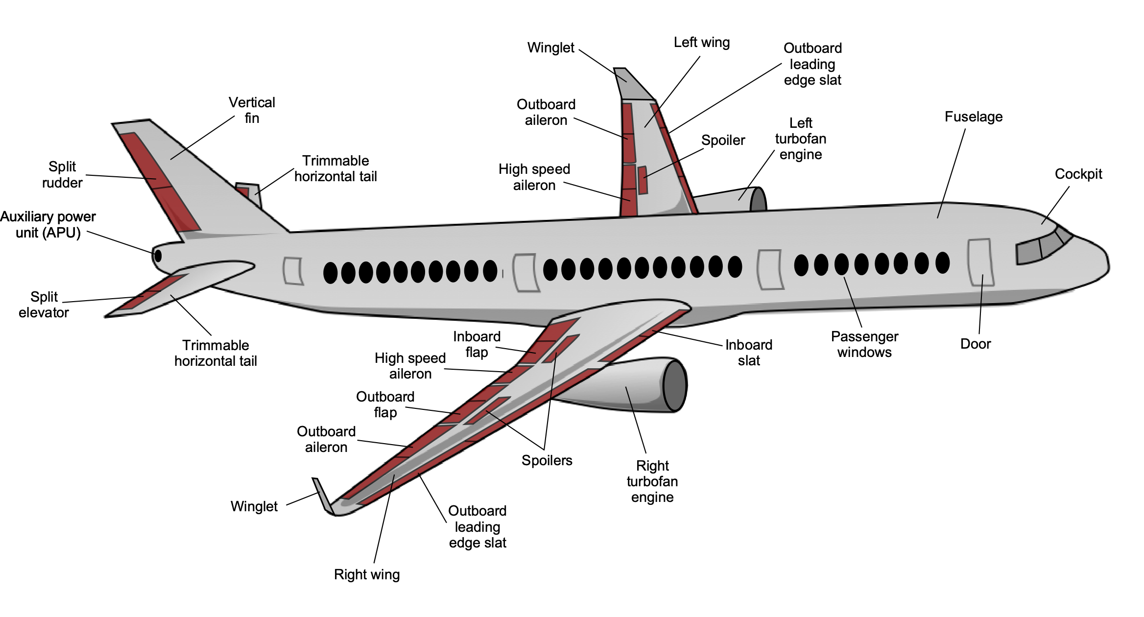
This page shows the parts of an airplane and their functions. Airplanes are transportation devices which are designed to move people and cargo from one place to another. Airplanes come in many different shapes and sizes depending on the mission of the aircraft. The airplane shown on this slide is a turbine-powered airliner which has been chosen as a representative aircraft.
For any airplane to fly, you must lift the weight of the airplane itself, the fuel, the passengers, and the cargo. The wings generate most of the lift to hold the plane in the air. To generate lift, the airplane must be pushed through the air. The jet engines, which are located beneath the wings, provide the thrust to push the airplane forward through the air. The air resists the motion in the form of aerodynamic drag. Some airplanes use propellers for the propulsion system instead of jets.
To control and maneuver the aircraft, smaller wings are located at the tail of the plane. The tail usually has a fixed horizontal piece (called the horizontal stabilizer) and a fixed vertical piece (called the vertical stabilizer). The stabilizers' job is to provide stability for the aircraft, to keep it flying straight. The vertical stabilizer keeps the nose of the plane from swinging from side to side, while the horizontal stabilizer prevents an up-and-down motion of the nose. (On the Wright brother's first aircraft, the horizontal stabilizer was placed in front of the wings. Such a configuration is called a canard after the French word for "duck").
At the rear of the wings and stabilizers are small moving sections that are attached to the fixed sections by hinges. In the figure, these moving sections are colored brown. Changing the rear portion of a wing will change the amount of force that the wing produces. The ability to change forces gives us a means of controlling and maneuvering the airplane. The hinged part of the vertical stabilizer is called the rudder; it is used to deflect the tail to the left and right as viewed from the front of the fuselage. The hinged part of the horizontal stabilizer is called the elevator; it is used to deflect the tail up and down. The outboard hinged part of the wing is called the aileron; it is used to roll the wings from side to side. Most airliners can also be rolled from side to side by using the spoilers. Spoilers are small plates that are used to disrupt the flow over the wing and to change the amount of force by decreasing the lift when the spoiler is deployed.
The wings have additional hinged, rear sections near the body that are called flaps. Flaps are deployed downward on takeoff and landing to increase the amount of force produced by the wing. On some aircraft, the front part of the wing will also deflect. Slats are used at takeoff and landing to produce additional force. The spoilers are also used during landing to slow the plane down and to counteract the flaps when the aircraft is on the ground. The next time you fly on an airplane, notice how the wing shape changes during takeoff and landing.
The fuselage or body of the airplane, holds all the pieces together. Passengers and cargo are carried in the rear of the fuselage. Some aircraft carry fuel in the fuselage; others carry the fuel in the wings.
As mentioned above, the aircraft configuration in the figure was chosen only as an example. Individual aircraft may be configured quite differently from this airliner. The Wright Brothers 1903 Flyer had pusher propellers and the elevators at the front of the aircraft. Fighter aircraft often have the jet engines buried inside the fuselage instead of in pods hung beneath the wings. Many fighter aircraft also combine the horizontal stabilizer and elevator into a single stabilator surface. There are many possible aircraft configurations, but any configuration must provide for the four forces needed for flight.
It appears to me that if one wants to make progress in mathematics, one should study the masters and not the pupils. - Niels Henrik Abel.
Nothing is better than reading and gaining more and more knowledge - Stephen William Hawking.
Offline
Pages: 1