Math Is Fun Forum
You are not logged in.
- Topics: Active | Unanswered
#2651 2025-11-19 16:39:14
- Jai Ganesh
- Administrator

- Registered: 2005-06-28
- Posts: 53,831
Re: Miscellany
2451) Ozone
Gist
Ozone (O3) is a gas with a distinct odor that exists in two layers of the atmosphere: the protective stratospheric ozone layer and the harmful ground-level ozone. While stratospheric ozone is beneficial because it shields the Earth from the sun's harmful ultraviolet (UV) radiation, ground-level ozone is a major air pollutant and a key component of smog that can cause serious health problems. Ground-level ozone forms when pollutants from sources like car exhaust and industrial emissions react with sunlight.
Ozone (O3) is a gas with a chemical formula of O3, meaning it has three oxygen atoms instead of the two in the oxygen we breathe (O2). It can be "good" or "bad" depending on its location in the atmosphere: "good" stratospheric ozone forms a protective layer that shields Earth from the sun's harmful ultraviolet (UV) radiation, while "bad" ground-level ozone is a pollutant that can damage lungs and crops.
Summary
Ozone, also called trioxygen, is an inorganic molecule with the chemical formula O3. It is a pale-blue gas with a distinctively pungent odour. It is an allotrope of oxygen that is much less stable than the diatomic allotrope O2, breaking down in the lower atmosphere to O2 (dioxygen). Ozone is formed from dioxygen by the action of ultraviolet (UV) light and electrical discharges within the Earth's atmosphere. It is present in very low concentrations throughout the atmosphere, with its highest concentration high in the ozone layer of the stratosphere, which absorbs most of the Sun's ultraviolet (UV) radiation.
Ozone's odour is reminiscent of chlorine, and detectable by many people at concentrations of as little as 0.1 ppm in air. Ozone's O3 structure was determined in 1865. The molecule was later proven to have a bent structure and to be weakly diamagnetic. At standard temperature and pressure, ozone is a pale blue gas that condenses at cryogenic temperatures to a dark blue liquid and finally a violet-black solid. Ozone's instability with regard to more common dioxygen is such that both concentrated gas and liquid ozone may decompose explosively at elevated temperatures, physical shock, or fast warming to the boiling point. It is therefore used commercially only in low concentrations.
Ozone is a powerful oxidising agent (far more so than dioxygen) and has many industrial and consumer applications related to oxidation. This same high oxidising potential, however, causes ozone to damage mucous and respiratory tissues in animals, and also tissues in plants, above concentrations of about 0.1 ppm. While this makes ozone a potent respiratory hazard and pollutant near ground level, a higher concentration in the ozone layer (from two to eight ppm) is beneficial, preventing damaging UV light from reaching the Earth's surface.
Details
Ozone, (O3), triatomic allotrope of oxygen (a form of oxygen in which the molecule contains three atoms instead of two as in the common form) that accounts for the distinctive odor of the air after a thunderstorm or around electrical equipment. The odor of ozone around electrical machines was reported as early as 1785; ozone’s chemical constitution was established in 1872. Ozone is an irritating pale blue gas that is explosive and toxic, even at low concentrations. It occurs naturally in small amounts in Earth’s stratosphere, where it absorbs solar ultraviolet radiation, which otherwise could cause severe damage to living organisms on Earth’s surface. Under certain conditions, photochemical reactions between nitrogen oxides and hydrocarbons in the lower atmosphere can produce ozone in concentrations high enough to cause irritation of the eyes and mucous membranes. Such ground-level ozone is considered a major air pollutant.
Ozone usually is manufactured by passing an electric discharge through a current of oxygen or dry air. The resulting mixtures of ozone and original gases are suitable for most industrial purposes, although purer ozone may be obtained from them by various methods; for example, upon liquefaction, an oxygen-ozone mixture separates into two layers, of which the denser one contains about 75 percent ozone. The extreme instability and reactivity of concentrated ozone makes its preparation both difficult and hazardous.
Ozone is 1.5 times as dense as oxygen; at −112 °C (−170 °F) it condenses to a dark blue liquid, which freezes at −251.4 °C (−420 °F). The gas decomposes rapidly at temperatures above 100 °C (212 °F) or, in the presence of certain catalysts, at room temperatures. Although it resembles oxygen in many respects, ozone is much more reactive; hence, it is an extremely powerful oxidizing agent, particularly useful in converting olefins into aldehydes, ketones, or carboxylic acids. Because it can decolorize many substances, it is used commercially as a bleaching agent for organic compounds; as a strong germicide it is used to sterilize drinking water as well as to remove objectionable odors and flavors.
Additional Information
Ozone (O3) is a highly reactive gas composed of three oxygen atoms. It is both a natural and a man-made product that occurs in the Earth's upper atmosphere (the stratosphere) and lower atmosphere (the troposphere). Depending on where it is in the atmosphere, ozone affects life on Earth in either good or bad ways.
Stratospheric ozone is formed naturally through the interaction of solar ultraviolet (UV) radiation with molecular oxygen (O2). The "ozone layer," approximately 6 through 30 miles above the Earth's surface, reduces the amount of harmful UV radiation reaching the Earth's surface.
Tropospheric or ground-level ozone – what we breathe – is formed primarily from photochemical reactions between two major classes of air pollutants, volatile organic compounds (VOC) and nitrogen oxides (NOx). These reactions have traditionally been viewed as depending upon the presence of heat and sunlight, resulting in higher ambient ozone concentrations in summer months. Within the last decade, however, high ozone concentrations have also been observed under specific circumstances in cold months, where a few high elevation areas in the Western U.S. with high levels of local VOC and NOx emissions have formed ozone when snow is on the ground and temperatures are near or below freezing. Ozone contributes to what we typically experience as "smog" or haze, which still occurs most frequently in the summertime, but can occur throughout the year in some southern and mountain regions.
Although some stratospheric ozone is transported into the troposphere, and some VOC and NOx occur naturally, the majority of ground-level ozone is the result of reactions of man-made VOC and NOx. Significant sources of VOC are chemical plants, gasoline pumps, oil-based paints, autobody shops, and print shops. Nitrogen oxides result primarily from high temperature combustion. Significant sources are power plants, industrial furnaces and boilers, and motor vehicles.
Ozone has two properties of interest to human health. First, it absorbs UV light, reducing human exposure to harmful UV radiation that causes skin cancer and cataracts. Second, when inhaled, it reacts chemically with many biological molecules in the respiratory tract, leading to a number of adverse health effects. This course addresses this second property.
Ozone (O3) is a gas molecule composed of three oxygen atoms which occur both in the Earth's upper atmosphere and at ground level. There is both a "good" and "bad" Ozone.
Bad Ozone - Ground-level Ozone is an air pollutant that is harmful to breathe and damages crops, trees, and other vegetation. It is the main ingredient of urban smog. The Centers for Disease Control and Prevention (CDC) states that breathing ground-level ozone can be harmful to your health.
Good Ozone - Ozone is produced naturally in the stratosphere. But this "good" ozone layer is gradually being destroyed by man-made chemicals referred to as ozone-depleting substances (ODS). Essentially, Ozone is only good for our stratosphere, which is a layer of the earth's protective barrier.

It appears to me that if one wants to make progress in mathematics, one should study the masters and not the pupils. - Niels Henrik Abel.
Nothing is better than reading and gaining more and more knowledge - Stephen William Hawking.
Offline
#2652 2025-11-27 22:27:18
- Jai Ganesh
- Administrator
- Registered: 2005-06-28
- Posts: 53,831
Re: Miscellany
2452) Seebeck Effect
Gist
Seebeck effect, production of an electromotive force (emf) and consequently an electric current in a loop of material consisting of at least two dissimilar conductors when two junctions are maintained at different temperatures. The conductors are commonly metals, though they need not even be solids. The German physicist Thomas Johann Seebeck discovered (1821) the effect. The Seebeck effect is used to measure temperature with great sensitivity and accuracy and to generate electric power for special applications.
Summary
The Seebeck effect is the direct conversion of temperature differences into electrical voltage, generated when two different conductors or semiconductors are joined to form a loop. This phenomenon creates a small voltage, called the Seebeck voltage, which can be used for practical applications like generating electricity from heat using thermoelectric generators or measuring temperature with thermocouples.
The Seebeck effect is the phenomenon where a temperature difference between two different conductors or semiconductors creates an electrical voltage. This direct conversion of thermal energy to electrical energy is the principle behind thermoelectric devices like thermocouples, which use a temperature gradient to generate a measurable voltage.
Details:
Key learnings:
Seebeck Effect Definition: The Seebeck effect is defined as the conversion of temperature differences into electric voltage, enabling various practical applications.
Temperature to Electricity: This effect generates electricity when there is a temperature difference across the junctions of two different materials.
Key Applications: Thermocouples and thermoelectric generators are primary applications, used for temperature measurement and converting waste heat into power.
Material Requirements: Effective materials for the Seebeck effect include metals with low Seebeck coefficients and semiconductors with higher coefficients for better performance.
Advantages and Challenges: While the Seebeck effect is reliable and can harness low-grade heat, finding materials with the right properties remains a significant challenge.
The Seebeck effect is a phenomenon that converts temperature differences into electric voltage and vice versa. It is named after Thomas Johann Seebeck, a German physicist who discovered it in 1821. The Seebeck effect is the basis of thermocouples, thermoelectric generators, and spin caloritronics.
Thomas Seebeck:
What is the Seebeck Effect?
The Seebeck effect is defined as the generation of an electric potential (or voltage) across two different conductors or semiconductors that are connected in a loop and have a temperature difference between their junctions. The voltage is proportional to the temperature difference and depends on the materials used.
For example, a thermocouple is a device that uses the Seebeck effect to measure temperature. It consists of two wires made of different metals (such as copper and iron) that are joined at both ends. One end is exposed to a hot source (such as a flame) and the other end is kept cold (such as in ice water). The temperature difference between the ends creates a voltage across the wires, which can be measured by a voltmeter.
The Seebeck effect also enables the generation of electricity from waste heat. In a thermoelectric generator, multiple thermocouples are linked either in series or parallel. These thermocouples have one side connected to a heat source—like an engine or furnace—and the other to a heat sink, such as air or water. This temperature differential generates a voltage capable of powering electrical devices, such as lights or fans.
How Does the Seebeck Effect Work?
Electrons, which are negatively charged and move freely in conductors and semiconductors, drive the Seebeck effect. When these materials are heated, the electrons gain energy and move from the hot area to the cooler one, generating an electric current as they travel.
However, different materials have different numbers and types of electrons available for conduction. Some materials have more electrons than others, and some have electrons with different spin orientations. Spin is a quantum property of electrons that makes them act like tiny magnets. When two materials with different electron characteristics are joined together, they form an interface where electrons can exchange energy and spin.
The Seebeck effect occurs when two such interfaces are subjected to a temperature difference. The electrons at the hot interface gain more energy and spin from the heat source and transfer them to the electrons at the cold interface through the loop. This creates an imbalance of charge and spin between the interfaces, resulting in an electric potential and a magnetic field. The electric potential drives an electric current through the loop, while the magnetic field deflects a compass needle placed near it.
What are the Applications of the Seebeck Effect?
The Seebeck effect has many applications in science, engineering, and technology. Some of them are:
* Thermocouples: These are devices that use the Seebeck effect to measure temperature with high accuracy and sensitivity. They are widely used in industries, laboratories, and households for various purposes, such as controlling ovens, monitoring engines, measuring body temperature, etc.
* Thermoelectric generators: These are devices that use the Seebeck effect to convert waste heat into electricity for special applications, such as powering spacecraft, remote sensors, medical implants, etc.
* Spin caloritronics: This is a branch of physics that studies how heat and spin interact in magnetic materials. The Seebeck effect plays an important role in this field, as it can create spin currents and voltages from temperature gradients. This can lead to novel devices for information processing and storage, such as spin batteries, spin transistors, spin valves, etc.
What are the Advantages and Limitations of the Seebeck Effect?
The Seebeck effect has some advantages and limitations that affect its performance and efficiency. Some of them are:
Advantages: The Seebeck effect is simple, reliable, and versatile. It does not require any moving parts or external power sources. It can operate over a wide range of temperatures and materials. It can generate electricity from low-grade heat sources that would otherwise be wasted.
Limitations: The Seebeck effect is limited by the availability and compatibility of materials. It requires materials with high electrical conductivity and low thermal conductivity to achieve high voltage and low heat loss. It also requires materials with different Seebeck coefficients to create a voltage difference. The Seebeck coefficient is a property that measures how much voltage is generated per unit temperature difference for a given material. The Seebeck coefficient depends on the type and concentration of charge carriers, their energy levels, and their interactions with the lattice. The Seebeck coefficient can vary with temperature, composition, and magnetic field. Finding materials with high and stable Seebeck coefficients is a challenge for thermoelectric applications.
What are the Types of Materials Used for the Seebeck Effect?
The materials used for the Seebeck effect can be classified into three categories: metals, semiconductors, and superconductors.
* Metals: Metals are good conductors of both electricity and heat. They have low Seebeck coefficients and high thermal conductivity, which makes them inefficient for thermoelectric applications. However, metals are easy to fabricate and connect, and they have high mechanical strength and stability. Metals are commonly used for thermocouples, where accuracy and durability are more important than efficiency. Some examples of metal pairs used for thermocouples are copper-constantan, iron-constantan, chromel-alumel, etc.
* Semiconductors: Semiconductors are materials that have an intermediate electrical conductivity that can be controlled by doping or applying an electric field. They have higher Seebeck coefficients and lower thermal conductivity than metals, which makes them more suitable for thermoelectric applications. However, semiconductors are more difficult to fabricate and connect, and they have lower mechanical strength and stability than metals. Semiconductors are commonly used for thermoelectric generators and coolers, where efficiency and performance are more important than accuracy and durability. Some examples of semiconductor pairs used for thermoelectric devices are bismuth telluride-antimony telluride, lead telluride-silicon germanium, etc.
* Superconductors: Superconductors are materials that have zero electrical resistance below a critical temperature. They have very high Seebeck coefficients and very low thermal conductivity, which makes them ideal for thermoelectric applications. However, superconductors are very rare and expensive, and they require very low temperatures to operate, which limits their practical use. Superconductors are mainly used for research purposes, such as studying the spin Seebeck effect, which is a phenomenon that involves the generation of a spin voltage from a temperature gradient in a magnetic material.
Conclusion
The Seebeck effect, which transforms temperature differences into electrical voltage, plays a crucial role in devices like thermocouples and thermoelectric generators. Its efficiency hinges on the materials used—specifically their conductivity and Seebeck coefficients. Despite challenges in material selection, its potential in various fields remains substantial.
Additional Information
The Seebeck effect is a phenomenon in which a temperature difference between two dissimilar electrical conductors or semiconductors produces a voltage difference between the two substances.
When heat is applied to one of the two conductors or semiconductors, heated electrons flow toward the cooler conductor or semiconductor. If the pair is connected through an electrical circuit, direct current (DC) flows through that circuit.
Seebeck effect: Key findings
The Seebeck effect refers to the buildup of electric potential which happens when there is a temperature gradient between different electrical conductors or semiconductors.
Here are some key findings of this phenomenon:
* The voltages produced by the Seebeck effect are small, usually only a few microvolts (millionths of a volt) per kelvin of temperature difference at the junction between the conductors or semiconductors.
* If the temperature difference is large enough, some Seebeck-effect devices can produce a few millivolts (thousandths of a volt).
* Numerous such devices can be connected in series to increase the output voltage or in parallel to increase the maximum deliverable current.
* Large arrays of Seebeck-effect devices can provide useful, small-scale electrical power if a large temperature difference is maintained across the junctions.
Seebeck effect: Explanation
In 1821, German physicist Thomas Seebeck discovered that when two wires made from dissimilar metals are joined at two ends to form a loop, and if the two junctions are maintained at different temperatures, a voltage develops in the circuit. This phenomenon is therefore named after him.
When heat is applied to one of the two conductors or semiconductors, that metal heats up. Consequently, the valence electrons present in this metal flow toward the cooler metal. This happens because electrons move to where energy (in this case, heat) is lower. If the metals are connected through an electrical circuit, direct current flows through the circuit.
However, this voltage is just a few microvolts per kelvin temperature difference. Thermal energy is continuously transferred from the warmer metal to the cooler metal until eventually, temperature equilibrium is obtained.
The Seebeck effect and its resultant thermoelectric effect is a reversible process. If the hot and cold junctions are interchanged, valence electrons will flow in the other direction, and also change the direction of the DC current.
Seebeck effect and thermocouples
The pair of metal wires forming the electrical circuit is known as a thermocouple. On a larger scale and due to the Seebeck effect, thermocouples are used to approximately measure temperature differences. They are also used to actuate electronic switches that can turn large systems on and off, a capability that is employed in thermoelectric cooling technology.
Seebeck used copper and bismuth in his experiment. Other common thermocouple metal combinations that are used today include the following:
* constantan and copper
* constantan and iron
* constantan and chromel
* constantan and alumel
Applications of Seebeck effect
There are many applications of the Seebeck effect. In addition to its use in thermocouples to measure temperature differences, the phenomenon is also used in the following ways:
* in thermopiles (that is, in a setting where a number of thermocouples are connected in series);
* in thermoelectric generators that function as heat engines;
* in power plants to convert waste heat into (extra) power;
* in automobiles as automotive thermoelectric generators, to increase fuel efficiency;
* in high-frequency electrical power sensors;
* to verify material degradation and radiation level, and to perform strength testing of radioactive materials (which vary with temperature over a given time period); and
* to actuate security alarms or switches.
Spin Seebeck effect
In 2008, physicists discovered the Spin Seebeck effect (SSE). This effect refers to the generation of a spin voltage caused by a temperature gradient in a ferromagnet. This gradient enables the thermal injection of spin currents from the ferromagnet into a nonmagnetic metal. This injection happens over a macroscopic scale of several millimeters.
SSE is seen when heat is applied to a magnetized metal. As a result, electrons rearrange themselves according to their spin. Unlike ordinary electron movement, this rearrangement does not create heat as a waste product.
The effect could lead to the development of smaller, faster and more energy-efficient microchips or switches, as well as spintronics devices.
Seebeck effect vs. Peltier effect
In 1834, Jean Peltier, a French watchmaker, discovered another second thermoelectric effect that was later named the Peltier effect. Peltier observed that when a current flows through a circuit containing a junction of two dissimilar metals -- similar to the setup in the Seebeck effect -- heat is either absorbed or liberated at the junction. This absorption or liberation depends on the pair of metals used and the direction of the current.
The Seebeck effect and Peltier effect both involve circuits made from dissimilar metals, as well as heat and electricity. Both are also reversible processes. But despite these similarities, there are some differences between these effects as well.
The Seebeck effect occurs when the two ends of a thermocouple are at different temperatures, which results in electricity flowing from the hot metal to the cold metal.
In the Peltier effect, a temperature difference is created between the junctions when electrical current flows across the terminals. In a copper-constantan thermocouple in which the current at the junction is flowing from copper (+) to constantan (-), heat will be absorbed. But if the direction of the current is reversed -- i.e., from constantan (-) to copper (+) -- it will result in heat liberation.

It appears to me that if one wants to make progress in mathematics, one should study the masters and not the pupils. - Niels Henrik Abel.
Nothing is better than reading and gaining more and more knowledge - Stephen William Hawking.
Offline
#2653 2025-12-03 14:05:57
- Jai Ganesh
- Administrator
- Registered: 2005-06-28
- Posts: 53,831
Re: Miscellany
2453) Parsec
Gist
A parsec is a unit of distance used in astronomy, equivalent to approximately 3.26 light-years. It is defined as the distance at which one astronomical unit (the average distance between the Earth and the Sun) subtends an angle of one arcsecond.
A parsec can be defined as the length of the right triangle side adjacent to the vertex occupied by a star whose parallax angle is one arcsecond.
Summary
The parsec (symbol: pc) is a unit of length used to measure the large distances to astronomical objects outside the Solar System, approximately equal to 3.26 light-years or 206,265 astronomical units (AU), i.e. 30.9 trillion kilometres (19.2 trillion miles).[a] The parsec unit is obtained by the use of parallax and trigonometry, and is defined as the distance at which 1 AU subtends an angle of one arcsecond (1/3600 of a degree). The nearest star, Proxima Centauri, is about 1.3 parsecs (4.2 light-years) from the Sun: from that distance, the gap between the Earth and the Sun spans slightly less than one arcsecond. Most stars visible to the naked eye are within a few hundred parsecs of the Sun, with the most distant at a few thousand parsecs, and the Andromeda Galaxy at over 700,000 parsecs.
The word parsec is a shortened form of a distance corresponding to a parallax of one second, coined by the British astronomer Herbert Hall Turner in 1913. The unit was introduced to simplify the calculation of astronomical distances from raw observational data. Partly for this reason, it is the unit preferred in astronomy and astrophysics, though in popular science texts and common usage the light-year remains prominent. Although parsecs are used for the shorter distances within the Milky Way, multiples of parsecs are required for the larger scales in the universe, including kiloparsecs (kpc) for the more distant objects within and around the Milky Way, megaparsecs (Mpc) for mid-distance galaxies, and gigaparsecs (Gpc) for many quasars and the most distant galaxies.
In August 2015, the International Astronomical Union (IAU) passed Resolution B2 which, as part of the definition of a standardized absolute and apparent bolometric magnitude scale, mentioned an existing explicit definition of the parsec as exactly 648000/{pi} au, or approximately 30856775814913673 metres, given the IAU 2012 exact definition of the astronomical unit in metres. This corresponds to the small-angle definition of the parsec found in many astronomical references.
Details
A parsec is a unit for expressing distances to stars and galaxies, used by professional astronomers. It represents the distance at which the radius of Earth’s orbit subtends an angle of one second of arc. Thus, a star at a distance of one parsec would have a parallax of one second, and the distance of an object in parsecs is the reciprocal of its parallax in seconds of arc. For example, the nearest star, Proxima Centauri, which is part of the Alpha Centauri triple-star system, has a parallax of 0.769 second of arc, and, hence, its distance from the Sun and Earth is 1.30 parsec. One parsec equals 3.26 light-years, which is equivalent to 3.09 × {10}^{13} km (1.92 × {10}^{13} miles).
In the Milky Way Galaxy, wherein Earth is located, distances to remote stars are measured in terms of kiloparsecs (1 kiloparsec = 1,000 parsecs). The Sun is at a distance of 8.3 kiloparsecs from the centre of the Milky Way system. When dealing with other galaxies or clusters of galaxies, the convenient unit is the megaparsec (1 megaparsec = 1,000,000 parsecs). The distance to the Andromeda Galaxy (Messier 31) is about 0.76 megaparsec. The farthest galaxies and quasars have distances on the order of about 4,000 megaparsecs, or 13,000,000,000 light-years.
Additional Information
If you ever heard professional astronomers talking among themselves, you wouldn’t hear much talk of light-years. The concept of a light-year – the distance light travels in a single earthly year, or about 6 trillion miles (nearly 10 trillion km) – is a great way to think about distance scales in the universe. But light-years aren’t as useful as parsecs when it comes to measuring those distances. A parsec – a unit of distance equal to about 19 trillion miles (more than 30 trillion km) – is more closely related to how astronomers go about the business of figuring out the size of the universe.
To find the distance to a nearby star, astronomers use triangulation. You can try it for yourself, right now. Hold your finger in front of your face, focus on something in the distance, and close first one eye, then the other eye. As you alternate eyes, you’ll notice your finger appears to dance back and forth in front of your face. The motion is, of course, an illusion. Your finger isn’t moving. Each eye sees your finger from a slightly different angle. So the finger’s location, relative to stuff in the background, looks different. This apparent shift is called parallax, from a Greek word meaning alternation.
These angles are miniscule. They’re too small for degrees to be a practical unit of measurement. That’s why parallax angles are typically measured in arcseconds – a unit of measurement equivalent to the width of an average human hair seen from 65 feet (20 meters) away – not degrees. There are 3,600 arcseconds in one degree.
And here’s how we arrive at parsecs as a unit of distance: one parsec is the distance to an object whose parallax angle is one arcsecond.
The term parsec is just over 100 years old. It first appeared in a 1913 paper by English astronomer Sir Frank Watson Dyson, and the term stuck. If you see a star with 1/2 arcsecond of parallax, it is two parsecs away. At 1/3 arcsecond, it is three parsecs away. And so on.
Basically, astronomers liked it because it made the math easier!
One parsec is approximately 19 trillion miles (30 trillion km). That’s a bit over three light-years. The Voyager 1 probe, launched in 1977, is the most distant manmade object from Earth. It is a mere six ten-thousandths of a parsec away. The nearest star to the sun, a small red dwarf named Proxima Centauri, is just over one parsec from us.
That is actually fairly typical in our neck of the galaxy – one star for every cubic parsec – but it’s not typical everywhere. In the cores of globular clusters, the density can reach well over a hundred stars per cubic parsec!
The center of the galaxy lies just over 8,000 parsecs from us in the direction of the constellation Sagittarius.
The Andromeda Galaxy, the closest spiral galaxy to our own, is nearly 800 kiloparsecs away. A kiloparsec is one thousand parsecs.
At larger scales, astronomers start to talk of megaparsecs and even gigaparsecs. That’s one million and one billion parsecs, respectively. These are generally reserved for the largest structures in existence. The Virgo Cluster, a conglomeration of thousands of galaxies towards which our own Local Group is falling, lies 16 megaparsecs from home. It would take 54 million years to reach it traveling at the speed of light.
It appears to me that if one wants to make progress in mathematics, one should study the masters and not the pupils. - Niels Henrik Abel.
Nothing is better than reading and gaining more and more knowledge - Stephen William Hawking.
Offline
#2654 2025-12-04 17:31:01
- Jai Ganesh
- Administrator
- Registered: 2005-06-28
- Posts: 53,831
Re: Miscellany
2454) Electric Bell
Gist
An electric bell is a device that uses an electromagnet to create a repetitive ringing sound. When the switch is pressed, an electric current flows, making the electromagnet attract an armature with a hammer. The hammer strikes the bell, but this action breaks the circuit, deactivates the electromagnet, and allows a spring to pull the armature back. The circuit is re-established, and the cycle repeats until the switch is released.
Principle: The electric bell works on the principle of electromagnetism — when an electric current flows through a coil, it behaves like a magnet and attracts a piece of iron. Working: When the switch is pressed, current flows through the electromagnet. The electromagnet pulls the iron armature towards it.
Summary
The electric bell contains an electromagnet, consisting of coils of insulated wire wound around iron rods. When an electric current flows through the coils, the rods become magnetic and attract a piece of iron attached to a clapper. The clapper hits the bell and makes it ring.
Working of an electric bell
Electric current flows through the coil when the switch is ON, and the iron core acts as an electromagnet. The iron core attracts the hammer towards it. The hammer hits the bell and produces a sound. The circuit breaks at the screw contact when the hammer moves towards the iron core. At this point, the iron core ceases to be an electromagnet. The hammer is pulled back to its original position due to the spring action of the steel rod and then touches the contact again to complete the circuit. The circuit is completed and current flows through the coil again, and the hammer strikes the bell again. The process repeats itself and you hear a ringing sound since the hammer keeps hitting the bell until the switch is released.
Details
An electric bell is a mechanical or electronic bell that functions by means of an electromagnet. When an electric current is applied, it produces a repetitive buzzing, clanging or ringing sound. Electromechanical bells have been widely used at railroad crossings, in telephones, fire and burglar alarms, as school bells, doorbells, and alarms in industrial areas, since the late 1800s, but they are now being widely replaced with electronic sounders. An electric bell consists of one or more electromagnets, made of a coil of insulated wire around an iron bar, which attract an iron strip armature with a clapper.
Types:
Interrupter bells
How they work
The most widely used form is the interrupter bell, which is a mechanical bell that produces a continuous sound when current is applied. See animation, above. The bell or gong (B), which is often in the shape of a cup or half-sphere, is struck by a spring-loaded arm (A) with a metal ball on the end called a clapper, actuated by an electromagnet (E). In its rest position the clapper is held away from the bell a short distance by its springy arm. When the switch (K) is closed, an electric current passes from the battery (U) through the winding of the electromagnet. It creates a magnetic field that attracts the iron arm of the clapper, pulling it over to give the bell a tap. This opens a pair of electrical contacts (T) attached to the clapper arm, interrupting the current to the electromagnet. The magnetic field of the electromagnet collapses, and the clapper springs away from the bell. This closes the contacts again, allowing the current to flow to the electromagnet again, so the magnet pulls the clapper over to strike the bell again. This cycle repeats rapidly, many times per second, resulting in a continuous ringing.
The tone of the sound generated depends on the shape and size of the bell or gong resonator. Where several bells are installed together, they may be given distinctive rings by using different size or shapes of gong, even though the strike mechanisms are identical.
Another type, the single-stroke bell, has no interrupting contacts. The hammer strikes the gong once each time the circuit is closed. These are used to signal brief notifications, such as a shop door opening for a customer, rather than continuous warnings.
Buzzers
An electric buzzer uses a similar mechanism to an interrupter bell, but without the resonant bell. They are quieter than bells, but adequate for a warning tone over a small distance, such as across a desktop.
A buzzer or beeper is an audio signalling device, which may be mechanical, electromechanical, or piezoelectric. Typical uses of buzzers and beepers include alarm devices, timers and confirmation of user input such as a mouse click or keystroke.
With the development of low cost electronics from the 1970s onwards, most buzzers have now been replaced by electronic 'sounders'. These replace the electromechanical striker of a bell with an electronic oscillator and a loudspeaker, often a piezoelectric transducer.
Single-stroke bells
The first commercial electric bells were used for railway signalling, between signal boxes. Complex bell codes were used to indicate the types of train passing between signal boxes, and the destinations to which they should be routed.
These were single-stroke bells: applying current to an electromagnet pulled the bell's clapper against the bell or gong and gave one chime. The bell did not ring continuously, but only with a single ring, until current was applied again. To sustain the tone, these bells were usually much larger than are used today with interrupter bells. Bells, gongs and spiral chimes could all be used, giving a distinct tone for each instrument.
A simple development of the single-stroke bell was the sprung bell. This had previously been used, mechanically actuated, for servant-call bells in large houses. Instead of working a clapper, the electromagnet shook the whole bell, which was mounted on a flexible spiral spring. The inertia of the heavy bell on the light spring would continue ringing for some seconds after the stroke. Although the sound would rapidly die away, the visible trembling of the bell could indicate which bell had been rung, amongst a panel of several.
Telephones
Landline telephone bells were powered by 60 to 500 volts RMS at between 16 and 25 Hertz AC. and a different design, the polarised bell, was used. These have an armature containing a permanent magnet, so that this is alternately attracted and repelled by each half-phase and different polarity of the supply. In practice, the armature is arranged symmetrically with two poles of opposite polarity facing each end of the coil, so that each may be attracted in turn. No contact breaker is required, so such bells are reliable for long service. In some countries, notably the UK, the clapper struck two different sized bells in turn giving a very distinctive ring.
Fire alarms
Fire alarm bells are divided into two categories: vibrating, and single-stroke. On a vibrating bell, the bell will ring continuously until the power is cut off. When power is supplied to a single-stroke bell, the bell will ring once and then stop. It will not ring again until power is turned off and on again. These were frequently used with coded pull stations.
Power sources
Electric bells are typically designed to operate on low voltages of from 5 to 24 V AC or DC. Before widespread distribution of electric power, bells were necessarily powered by batteries, either wet-cell or dry-cell type. Bells used in early telephone systems derived current by a magneto generator cranked by the subscriber. In residential applications, a small bell-ringing transformer is usually used to power the doorbell circuit. So that bell circuits can be made with low-cost wiring methods, bell signal circuits are limited in voltage and power rating. Bells for industrial purposes may operate on other, higher, AC or DC voltages to match plant voltages or available standby battery systems.
History
The interrupter bell evolved from various oscillating electromechanical mechanisms which were devised following the invention of the electromagnet by William Sturgeon in 1823. One of the first was the oscillating electric wire invented by James Marsh in 1824. This consisted of a wire pendulum dipping into a mercury trough, suspended between the poles of an electromagnet. When current was passed through the wire, the force of the magnet made the wire swing sideways, out of the mercury, which broke the current to the magnet, so the wire fell back. The modern electric bell mechanism had its origin in vibrating "contact breaker" or interrupter mechanisms devised to break the primary current in induction coils. Vibrating "hammer" interrupters were invented by Johann Philipp Wagner (1839) and Christian Ernst Neeff (1847), and was developed into a buzzer by Froment (1847). John Mirand around 1850 added a clapper and gong to make the standard electric bell for use as a telegraph sounder. Other types were invented around that time by Siemens and Halske and by Lippens. The polarized (permanent magnet) bell used in telephones, which appeared about 1860, had its beginning in the polarized relay and telegraph developed by Werner Siemens around 1850.
Additional Information:
Electric bell
An electric bell is an electromechanical device that works with the help of an electromagnet. When an electric current is applied to a traditional bell, the to and fro movement of a small hammer on a gong produces the sound of a bell. As a result, an electric bell is a device that is used to signal the presence of a guest or visitor.
When the electric bells are rung these days, they can even play songs or tunes. These mechanical-electric bells have been widely used in schools, burglar alarms, railway crossings, telephones, and industries since the 19th century. The electric bell, a first-of-its-kind invention, is widely used as an electronic sounder around the world. An electric bell is made up of an electromagnet attached to a strip of iron that causes the hammer to strike the gong, causing it to ring.
Working principle of electric bell
The principle of electromagnetism, or the magnetic effect of current, governs the operation of an electric bell. Magnetic fields are associated with moving electric charges, according to the electromagnetism phenomenon. A magnetic field is created whenever an electric current flows through a conductor. The right-hand-thumb rule can be used to determine the direction of this magnetic field. This principle is used to make electromagnets. Electromagnets can be found in a variety of electronic devices, including televisions, radios, speakers, and even an electric bell.
Electromagnets
An electromagnet is a man-made magnet that generates a magnetic field when current flows through it. A wire wound in a coil makes up an electromagnet. When an electric current flows through a wire, it creates a magnetic field around it, making the wire act like an electromagnet. The magnetic field created by an electromagnet lasts as long as current flows through it. Increase the number of turns in the coil, increase the current through the coil, and wind the coil around a magnetic material like soft iron to strengthen the magnetic field of an electromagnet. As long as there is electric power across its ends, an electromagnet behaves similarly to a regular magnet. The magnetic field around the electromagnet vanishes when the electric power is turned off.

It appears to me that if one wants to make progress in mathematics, one should study the masters and not the pupils. - Niels Henrik Abel.
Nothing is better than reading and gaining more and more knowledge - Stephen William Hawking.
Offline
#2655 2025-12-06 17:03:02
- Jai Ganesh
- Administrator
- Registered: 2005-06-28
- Posts: 53,831
Re: Miscellany
2455) Marsupials
Gist
Marsupials are the group of mammals commonly thought of as pouched mammals (like the wallaby and kangaroo at left). They give live birth, but they do not have long gestation times like placental mammals.
A marsupial is a mammal known for giving birth to underdeveloped young that continue to develop in a pouch (marsupium) on the mother's belly, feeding from teats inside. Key examples include kangaroos, koalas, opossums, and wombats, primarily found in Australia, though opossums are the only native U.S. species. Their young, called joeys, are born tiny and crawl into the pouch to nurse and grow, and they often have unique features like strong hind legs for hopping or specialized teeth.
Summary
Marsupials are a diverse group of mammals belonging to the infraclass Marsupialia. They are natively found in Australasia, Wallacea, and the Americas. One of marsupials' unique features is their reproductive strategy: the young are born in a relatively undeveloped state and then nurtured within a pouch on their mother's abdomen.
Extant marsupials encompass many species, including kangaroos, koalas, opossums, possums, Tasmanian devils, wombats, wallabies, and bandicoots.
Marsupials constitute a clade stemming from the last common ancestor of extant Metatheria, which encompasses all mammals more closely related to marsupials than to placentals. The evolutionary split between placentals and marsupials occurred 125–160 million years ago in the Middle Jurassic–Early Cretaceous period.
Presently, close to 70% of the 334 extant marsupial species are concentrated on the Australian continent, including mainland Australia, Tasmania, New Guinea, and nearby islands. The remaining 30% are distributed across the Americas, primarily in South America, with thirteen species in Central America and a single species, the Virginia opossum, inhabiting North America north of Mexico.
Marsupial sizes range from a few grams in the long-tailed planigale, to several tons in the extinct Diprotodon.
The word marsupial comes from marsupium, the technical term for the abdominal pouch. It, in turn, is borrowed from the Latin marsupium and ultimately from the ancient Greek mársippos, meaning "pouch".
Details
A marsupial is any of more than 250 species belonging to the infraclass Metatheria (sometimes called Marsupialia), a mammalian group characterized by premature birth and continued development of the newborn while attached to the nipples on the mother’s lower belly. The pouch—or marsupium, from which the group takes its name—is a flap of skin covering the nipples. Although prominent in many species, it is not a universal feature. In some species the nipples are fully exposed or are bounded by mere remnants of a pouch. The young remain firmly attached to the milk-giving teats for a period corresponding roughly to the latter part of development of the fetus in the womb of a placental mammal (eutherian).
The largest and most-varied assortment of marsupials—some 200 species—is found in Australia, New Guinea, and neighbouring islands, where they make up most of the native mammals found there. In addition to larger species such as kangaroos, wallabies, wombats, and the koala (Phascolarctos cinereus), there are numerous smaller forms, many of which are carnivorous, with the Tasmanian devil (Sarcophilus harrisii) being the largest of this group (family Dasyuridae). About 70 species live in the Americas, mainly in South and Central America, but one, the Virginia opossum (Didelphis virginiana), ranges through the United States into Canada. The largest living marsupial is the red kangaroo (Macropus rufus), males of which can grow to about 2 metres (6.6 feet) in height, 3 metres (10 feet) from muzzle to tail tip, and a weight of up to 90 kg (about 200 pounds). The smallest are the planigales (see marsupial mouse), especially the long-tailed planigale (Planigale ingrami), measuring barely 12 cm (4.7 inches) in total length. Most marsupials range from the size of a squirrel to that of a medium-size dog.
The structural and behavioral parallels with placental mammals are sometimes quite striking. Such resemblances are examples of convergent evolution—a tendency for organisms to adapt in similar ways to similar habitats. Thus, there are marsupials that look remarkably like moles, shrews, squirrels, mice, dogs, and hyenas. Others are the ecological counterparts, less in structure than in habits, of cats, small bears, and rabbits. Even the larger grazing marsupials (such as kangaroos), which resemble no placental mammals, can be thought of as filling the same ecological role (niche) as the deer and antelope found elsewhere.
The niches that marsupials fill are closely associated with structure. The burrowing species, such as the marsupial moles (Notoryctes typhlops and N. caurinus) and the wombats, have powerful foreclaws with which they can tunnel into the ground for food and shelter. Terrestrial forms, such as kangaroos and wallabies, possess well-developed hind limbs that serve both as formidable weapons and as catapults by which they can bound over the plains. The gliders have a membrane along either flank, attached to the forelegs and hind legs, that enables these arboreal animals to glide down from a high perch. A few marsupials—such as tree kangaroos, koalas, and some cuscuses—spend most of their lives in trees. The water opossum, or yapok (Chironectes minimus), of Central and South America is semiaquatic.
The diets of marsupials are as varied as the niches they occupy. Many dasyurids live chiefly on insects and other small animals. Dunnarts (Sminthopsis) are so hyperactive—like shrews—that, in order to supply their high energy needs, they must devour their own weight in food (chiefly insects) each day. The numbat uses its remarkable wormlike tongue to lap up termites and ants. Many Australian possums, bandicoots, and American opossums have a mixed diet of plants and insects. Wombats and many other marsupials are strictly vegetarian. The small honey possum (Tarsipes rostratus) is specialized to feed on the nectar of flowers, and other marsupials also may serve as important pollinators in that way. Few large carnivores have ever evolved in Australia, because of the low productivity of its environment. The most-recent large carnivorous marsupials to evolve—the Tasmanian devil and the now-extinct thylacine, or Tasmanian wolf (Thylacinus cynocephalus)—were both displaced on the mainland by the dingo.
Marsupials are notably less intelligent than placental mammals, partly because of their simpler brains. Compared with that of placentals, the brain of marsupials differs markedly in both structure and bulk. Most notably, it lacks a corpus callosum, the part of the placental brain that connects the two cerebral halves. The marsupial brain is also smaller relative to overall body size; for example, a quoll has about half as much brain tissue as a placental cat of similar skull size. It is not surprising, therefore, to find that marsupial behaviour differs somewhat from that of placentals. One peculiarity that may stem from that underdevelopment is restricted vocal ability. Although marsupials are not entirely silent, few emit loud sounds of excitement or distress; apparently, none utters grunts of contentment or even cries of hunger when young. Their vocalizing is more limited and less variable than that of placentals. The ferocious-sounding rutting roars of male koalas are a dramatic and unexpected exception.
There seems to be little permanent social organization among most marsupials beyond short-lived pair bonds during mating. Many of the grazing marsupials, such as kangaroos and wallabies, move in feeding groups called mobs, but those associations are not true social groups, as there is no attention paid to any leaders or elders. Only the lesser gliders (Petaurus) have permanent cohesive social groupings.
The life cycle of marsupials exhibits peculiarities that have long been considered primitive compared with those of placental mammals but are more likely adaptations to low-productivity environments. The uterine cycle of the female marsupial has no secretory phase, and the uterine wall is not specialized for embryo implantation, although a transitory placenta does exist in the bandicoots. The period of intrauterine development in marsupials ranges from about 12 days in the bilby (Macrotis lagotis) to 38 days in the swamp wallaby (Wallabia bicolor).
The young, born in a vulnerable embryonic condition, make their own way to the shelter, warmth, and nourishment of the pouch; in pouchless marsupials the young simply cling to the teats. Those fortunate enough to survive that arduous journey may succeed in attaching themselves to the mother’s nipples, which then swell and become firmly fastened—almost physically fused—to the mouth tissues of the young. In that condition the young continue their development for weeks or months, after which they are weaned and begin to look after themselves. Frequently, the partially developed young outnumber the available teats, and the excess individuals perish.
Additional Information
There are over 330 species of marsupials. Around two-thirds of them live in Australia. The other third live mostly in South America
A marsupial is born in a very incomplete state. They are minute, blond, hairless and with hindlimbs only partially formed. The forelimbs however are developed, and the toes are armed with sharp, curved claws. They use these claws to make the journey to the pouch, many times the body length of the one month old foetus.
Marsupials have a short-lived placenta that nourishes their young for just a few days before they’re born, the rest of their nutrition coming from the mother’s teats inside the pouch. Instead of the placenta, the mother’s milk nourishes the young and allows it to grow and develop.
Although the word ‘marsupial’ comes from the Latin word ‘marsupium’, which means pouch, not all marsupials have pouches. The pouch is designed to protect the offspring while they suckle on the nipples, however some in some species this is just a fold, not something the young can fit inside for their joey stage of development.
Marsupials have an extra pubic bone, the epipubic bone, to support their pouch.
The toes of many marsupials appear conjoined with webbing, a mutation known as syndactyly. The koala is a perfect example.
Australian marsupials can be categorised by what they eat into 3 groups:
Dasyurids - these are the meat-eating marsupials: quolls, the tamanian devil, tasmanian tiger, numbats, dunnarts, antechinus.
Peramelemorphs - these are the omnivorous marsupials: bilbies and bandicoots.
Diprotodonts - these are the largely herbivorous marsupials: kangaroos, wallabies, possums, koalas, wombats.

It appears to me that if one wants to make progress in mathematics, one should study the masters and not the pupils. - Niels Henrik Abel.
Nothing is better than reading and gaining more and more knowledge - Stephen William Hawking.
Offline
#2656 2025-12-07 17:55:14
- Jai Ganesh
- Administrator
- Registered: 2005-06-28
- Posts: 53,831
Re: Miscellany
2456) Electric Eel
Gist
Electric eels produce electricity using thousands of stacked, disc-like cells called electrocytes, modified muscle cells that act like tiny batteries, creating a voltage difference. When triggered by the nervous system, these cells discharge simultaneously, sending a strong electrical pulse through the water for stunning prey or defense, similar to a biological battery pack.
They are known for their ability to stun their prey by generating electricity, delivering shocks at up to 860 volts. Their electrical capabilities were first studied in 1775, contributing to the invention of the electric battery in 1800.
Summary
The electric eel gets its name from its shocking abilities! Special organs in the eel’s body release powerful electric charges of up to 650 volts—that’s more than five times the power of a standard United States wall socket!
Physical Description
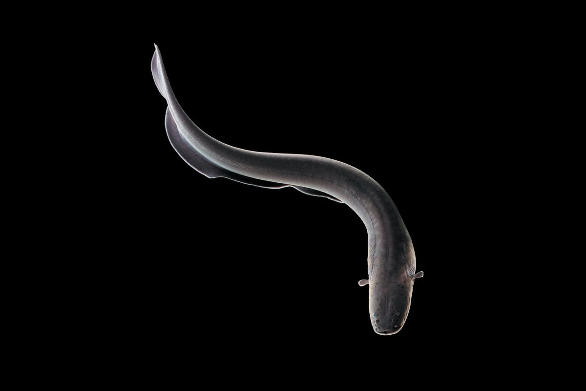
The electric eel has a slender, snake-like body and flattened head. Its thick, scaleless skin is generally dark gray to brown, and its underside is a yellow-orange color.
Similar to other eel shaped fish, the electric eel lacks pelvic fins. It has a small, or reduced, caudal fin and also lacks dorsal fins. Instead, an elongated anal fin helps it maneuver through the water, where it can swim forward, backward or hover, as it searches for prey.
Three specialized electric organs—the main electrical organ, the Hunter’s organ and the Sachs’ organ—make up about 80 percent of this fish’s body. Its remaining vital organs are tightly packed within the anterior, or front, part of its body.
The electric organs create strong and weak electric charges, which are utilized for defense, hunting, communication and navigation. Stronger electric charges can be energetically exhausting for this fish. Its strongest electric pulses are produced by the main electrical organ, as well as two-thirds of the Hunter’s organ. The remainder of the Hunter’s organ and the Sachs’ organ produce the weaker electric discharges.
Size
Electric eels grow to lengths of 6 to 8 feet (2 to 2.5 meters).
Native Habitat
This species is widely distributed across northern South America. Its range spans across Brazil, the Guianas, Suriname, Venezuela, Colombia, Ecuador and Peru. Electric eels inhabit the quiet, slow-moving waters of ox-bow lakes, streams, pools and flooded forests of the Amazon and Orinoco Rivers, preferring side channels but also living further inland.
Both of the rivers these fish inhabit are subject to a natural fluctuation of water driven by precipitation patterns, which results in two distinct seasons: wet and dry. The two seasons bring about drastic changes in available habitat for electric eels.
During the rainy season, the rivers swell, re-connecting lakes and ponds as the forests flood. Juvenile electric eels disperse and expand into new territories. As water recedes in the dry season, large groups of fish become isolated in the pools and smaller streams that remain.
The water in these areas is poorly oxygenated, but electric eels are specially adapted to thrive in this environment. They are obligate air-breathers, which means they surface for air periodically. Their mouths are heavily vascularized with folds that increase the surface area, allowing them to breathe air, rather than trying to meet their respiration needs through gills in warm, anoxic waters.
Throughout the dry season, the electric eel is also at greater risk from predators, such as large mammals, that hunt from outside the shallow waters it inhabits. Because there is little space to retreat, the fish is often forced to defend itself.
Water efficiently conducts electricity, providing a wide surface area for the electric eel’s shock to be applied. This means that an electric pulse delivered through the water may not be as painful for a large predator as one delivered outside of the water. As such, an electric eel can instead jump out of the water, sliding its body up against a partially submerged predator to directly target its shock. The eel then delivers its electric pulses in increasing voltages.
Lifespan
The average lifespan of electric eels in the wild is still unknown. In human care, males typically live 10 to 15 years, and females generally live 12 to 22 years.
Communication
Electric eels communicate using low electric organ discharges. This electricity is produced in pulses, and the duration of a pulse is much shorter than the time that lapses between each pulse. The frequency at which weaker electric pulses are produced varies between males and females, as well as across individuals.
Electric eels can detect these signals and interpret information about other individuals in the water. They can even convey information about their sex and sexual receptivity, which is important during the breeding season.
Electric eels are not the only fish to communicate using electric organ discharges. More than 220 species of South American knifefish in the electric eel's lineage use this highly advanced method of communication and detection.
Food/Eating Habits
Adult electric eels are generalist carnivores, eating fish, crustaceans, insects and small vertebrates, such as amphibians, reptiles and mammals. Juveniles feed primarily on invertebrates, and newly hatched electric eels will eat remaining, unhatched eggs.
In addition to defense, electric eels use their shocking power to hunt. In the dark and murky waters they inhabit, prey can be difficult to spot. To aid its hunt, the electric eel has motion-sensitive hairs along its body (the lateral line system) that detect any slight pressure change in the surrounding water. When the eel suspects a prey item is nearby, it emits two rapid electric pulses, called a doublet.
This doublet affects the muscles of the prey, causing it to twitch involuntarily and alerting the electric eel to its presence. With a series of high-voltage pulses (as many as 400 per second), it then paralyzes and consumes its prey. This entire process happens so quickly that it can be difficult for the human eye to observe in detail.
Reproduction and Development
Female electric eels lay between 1,200 and 1,700 eggs during the dry season. Males construct nests made of saliva and guard the larvae until the rainy season begins. This parental care may be the result of increased food competition and potential for predation during the dry season.
More research on the reproductive cycle and behavior of electric eels is needed to determine exactly how spawning takes place. Some researchers posit that spawning occurs in successive batches throughout the dry season, while other accounts document that all eggs are deposited at once.
Details
The electric eels are a genus, Electrophorus, of neotropical freshwater fish from South America in the family Gymnotidae, of which they are the only members of the subfamily Electrophorinae. They are known for their ability to stun their prey by generating electricity, delivering shocks at up to 860 volts. Their electrical capabilities were first studied in 1775, contributing to the invention of the electric battery in 1800.
Despite their name, electric eels are not closely related to the true eels (Anguilliformes) but are members of the electroreceptive knifefish order Gymnotiformes. This order is more closely related to catfish. In 2019, electric eels were split into three species: for more than two centuries before that, the genus was believed to be monotypic, containing only Electrophorus electricus.
They are nocturnal, obligate air-breathing animals, with poor vision complemented by electrolocation; they mainly eat fish. Electric eels grow for as long as they live, adding more vertebrae to their spinal column. Males are larger than females. Some captive specimens have lived for over 20 years.
Evolution:
Taxonomy
When electric eels were described by Carl Linnaeus in 1766, based on early field research by Europeans in South America and specimens sent back to Europe for study, he used the name Gymnotus electricus, placing it in the same genus as Gymnotus carapo (the banded knifefish). He noted that the fish is from the rivers of Surinam, that it causes painful shocks, and that it had small pits around the head.
In 1864, Theodore Gill moved the electric eel to its own genus, Electrophorus. The name is from the Greek (ḗlektron 'amber, a substance able to hold static electricity'), and (phérō 'I carry'), giving the meaning 'electricity bearer'. In 1872, Gill decided that the electric eel was sufficiently distinct to have its own family, Electrophoridae. In 1998, Albert and Campos-da-Paz lumped the Electrophorus genus with the family Gymnotidae, alongside Gymnotus, as did Ferraris and colleagues in 2017.
In 2019, C. David de Santana and colleagues divided E. electricus into three species based on DNA divergence, ecology and habitat, anatomy and physiology, and electrical ability. The three species are E. electricus (now in a narrower sense than before), and the two new species E. voltai and E. varii. However, this revision did not address Electrophorus multivalvulus, which was described from the Peruvian Amazon by Nakashima in 1941. Therefore, E. varii (described from the same region) may be a junior synonym of E. multivalvulus and has been regarded as such by some biologists.
Phylogeny
Electric eels form a clade of strongly electric fishes within the order Gymnotiformes, the South American knifefishes. Electric eels are thus not closely related to the true eels (Anguilliformes). The lineage of the Electrophorus genus is estimated to have split from its sister taxon Gymnotus sometime in the Cretaceous. Most knifefishes are weakly electric, capable of active electrolocation but not of delivering shocks. Their relationships, as shown in the cladogram, were analysed by sequencing their mitochondrial DNA in 2019. Actively electrolocating fish are marked with a small yellow lightning flash symbol for electrolocating fish. Fish able to deliver electric shocks are marked with a red lightning flash.
Additional Information
Electric eel, (genus Electrophorus), is any of three species of elongated South American knifefishes that produce powerful electric shocks to stun prey, usually other fish. All three species—the electric eel (Electrophorus electricus), Vari’s electric eel (E. varii), and Volta’s electric eel (E. voltai)—are found in the Amazon River or its tributaries.
Prey capture and electrical discharge
Electric eels have three electric organs—the main organ, Hunter’s organ, and Sach’s organ—which are made up of modified muscle cells. The main electric organ is located on the dorsal side; it spans the middle half of the body from just behind the head to the middle of the tail. Hunter’s organ parallels the main organ but on the ventral side. Those organs generate the high-voltage pulses that stun prey and deter predators. The rear quarter of the electric eel contains Sach’s organ, which produces lower-voltage pulses that allow the electric eel to communicate and navigate murky waters. Sach’s organ also contains the electric eel’s negative pole.
An electric eel can deliver a shock because its nervous system contains a number of disc-shaped electrogenic (electricity-producing) cells called electrocytes. Each electrocyte carries a net negative electric charge; the electrocyte’s inner periphery is negatively charged and has a potential difference of just under 100 millivolts relative to the deeper parts of the cell’s interior (which has a high concentration of positively charged potassium ions). When the shock command is delivered to these cells by the neurotransmitter acetylcholine, a path of low electrical resistance develops between one side of the cell and the interior. Through active transport (see cell: transport across the membrane), potassium ions outside the cell rush inward on that side, which causes some of the potassium ions inside the cell to exit the other side to maintain the cell’s equilibrium. With this process about 50 millivolts of electricity is released from the cell. Since the electrogenic cells are stacked next to one another, the activity of one cell firing sets off others around it, creating a cascade of current. The collective discharge of electricity from each electrocyte in the chain allows the electric eel to release up to 860 volts. Studies have shown that shocks from juvenile electric eels making leaping attacks can discharge more than 120 volts, which, after other factors are considered, can impart 40–50 milliamps of current on its victim, an amount large enough to cause intense pain in humans.
The electric eel’s penchant for shocking its prey may have evolved to protect its sensitive mouth from injury from often spiny struggling fish. The shocked prey is stunned long enough to be sucked through the mouth directly to the stomach. Sometimes the electric eel does not bother to stun prey but simply gulps faster than the prey can react. The electrical discharges also may be used to keep prey from escaping or to induce a twitching response in hidden prey that causes the prey to reveal its position. Such prey-capture tactics are commonly employed by single eels; however, at least one species also engages in social predation (pack hunting). Volta’s electric eels (E. voltai) coordinate their movements and the timing and strength of their electrical discharges to ambush or corral schools of fish before stunning and capturing individual prey.
Electric eels have been shown to curl their bodies around larger or more elusive prey. That strategy has the effect of doubling the strength of the electric field between the electric eel’s positive pole (which is located near the head) and its negative pole (which is located near the tail). The electric eel then delivers a series of shocks that occur at one-millisecond intervals. Each shock forces involuntary muscle contractions that fatigue the prey’s muscles, which allows the electric eel to better manipulate it for consumption.
Electric eels may also use their ability to shock other animals to defend themselves against predators and perceived threats. While an electric eel is fully submerged, its electrical discharge is weaker because the shock is distributed throughout the surrounding water. Stronger shocks, however, may be delivered by leaping out of the water or by extending the head up and out of the water to place the chin against a partially submerged animal. The strength of the electric current delivered in this fashion is not dampened by the watery medium. The electric current enters the animal’s body directly before traveling through the submerged parts of its body and back into the water to the tail of the electric eel, thereby completing the electric circuit.
Physical features
Long, cylindrical, scaleless, and usually gray-brown (sometimes with a red underside), electric eels can grow to 2.75 metres (9 feet) and weigh 22 kg (48.5 pounds). The tail region constitutes about four-fifths of an electric eel’s total length, which is bordered along the underside by an undulating anal fin that is used to propel the fish. Despite its name, it is not a true eel but is related to the characin fishes, which include piranhas and neon tetras.
Electric eels are sluggish creatures that prefer slow-moving fresh water, where they surface every few minutes to gulp air. Their mouth is rich with blood vessels that allow use of the mouth as a lung. The vestigial gills are used only to eliminate carbon dioxide, not for oxygen uptake.
Electric eels are among the principal aquatic predators of the white-water flooded forest known as varzea. In one fish survey of a typical varzea, electric eels made up more than 70 percent of the fish biomass. Electric eels also eat fruit that falls from trees whose canopies hang over rivers. Consequently, they aid in seed dispersal via defecation.
It appears to me that if one wants to make progress in mathematics, one should study the masters and not the pupils. - Niels Henrik Abel.
Nothing is better than reading and gaining more and more knowledge - Stephen William Hawking.
Offline
#2657 2025-12-08 16:22:02
- Jai Ganesh
- Administrator
- Registered: 2005-06-28
- Posts: 53,831
Re: Miscellany
2457) Snow Leopard
Gist
The snow leopard is also known as the ounce, from an old French word, and locally by names like "Shan" (Ladakhi) or "Bars" (Kazakh), but its most famous nickname is the "ghost of the mountains" due to its elusive nature. Its scientific name, Panthera uncia, reflects its connection to big cats, though it was once classified separately as Uncia uncia.
The snow leopard (Panthera uncia) is a species of large cat in the genus Panthera of the family Felidae.
Summary
The snow leopard (Panthera uncia) is a species of large cat in the genus Panthera of the family Felidae. The species is native to the mountain ranges of Central and South Asia. It is listed as Vulnerable on the IUCN Red List because the global population is estimated to number fewer than 10,000 mature individuals and is expected to decline about 10% by 2040. It is mainly threatened by poaching and habitat destruction following infrastructural developments. It inhabits alpine and subalpine zones at elevations of 3,000–4,500 m (9,800–14,800 ft), ranging from eastern Afghanistan, the Himalayas and the Tibetan Plateau to southern Siberia, Mongolia and western China. In the northern part of its range, it also lives at lower elevations.
Taxonomically, the snow leopard was long classified in the monotypic genus Uncia. Since phylogenetic studies revealed the relationships among Panthera species, it has since been considered a member of that genus. Two subspecies were described based on morphological differences, but genetic differences between the two have not yet been confirmed. It is therefore regarded as a monotypic species. The species is widely depicted in Kyrgyz culture.
(IUCN: International Union for Conservation of Nature ).
Details
Snow leopards have evolved to live in some of the harshest conditions on Earth. Their thick white-gray coat, spotted with large black rosettes, blends in perfectly with Asia’s steep and rocky, high mountains. Because of their incredible natural camouflage, rendering them almost invisible in their surroundings, snow leopards are often referred to as the “ghost of the mountains.”
The snow leopard’s powerful build allows it to scale great, steep slopes with ease. Its hind legs give the snow leopard the ability to leap six times the length of its body. A long tail enables agility, provides balance, and wraps around the resting snow leopard as protection from the cold.
For millennia, this magnificent cat was the king of the mountains. The mountains were rich with their prey, such as blue sheep, Argali wild sheep, ibex, marmots, pikas and hares. The snow leopard’s habitat range extends across the mountainous regions of 12 countries across Asia: Afghanistan, Bhutan, China, India, Kazakhstan, Kyrgyz Republic, Mongolia, Nepal, Pakistan, Russia, Tajikistan, and Uzbekistan. The total range covers an area of close to 772,204 square miles, with 60% of the habitat found in China. However, more than 70% of snow leopard habitat remains unexplored. Home range sizes can vary from 4.6-15.4 square miles in Nepal to over 193 square miles in Mongolia. And population density can range from <0.1 to 10 or more individuals per 38.6 square miles, depending on prey densities and habitat quality. Nevertheless, the snow leopard population is very likely declining.
Additional Information
A snow leopard is a large long-haired Asian cat, classified as either Panthera uncia or Uncia uncia in the family Felidae. The snow leopard inhabits the mountains of central Asia and the Indian subcontinent, ranging from an elevation of about 1,800 metres (about 6,000 feet) in the winter to about 5,500 metres (18,000 feet) in the summer.
Its soft coat, consisting of a dense insulating undercoat and a thick outercoat of hairs about 5 cm (2 inches) long, is pale grayish with dark rosettes and a dark streak along the spine. The underparts, on which the fur may be 10 cm (4 inches) long, are uniformly whitish. The snow leopard attains a length of about 2.1 metres (7 feet), including the 0.9-metre- (3-foot-) long tail. It stands about 0.6 metre (2 feet) high at the shoulder and weighs 23–41 kg (50–90 pounds). It hunts at night and preys on various animals, such as marmots, wild sheep, ibex (Capra), and domestic livestock. Its litters of two to four young are born after a gestation period of approximately 93 days.
Formerly classified as Leo uncia, the snow leopard has been placed—with the lion, tiger, and other big cats—in the genus Panthera. Because of the presence of certain skeletal features, such as having a shorter skull and having more-rounded eye orbits than other big cats, the snow leopard has also been classified by some authorities as the sole member of the genus Uncia. Genetic studies show that the common ancestor of snow leopards and tigers diverged from the lineage of big cats about 3.9 million years ago and that snow leopards branched from tigers about 3.2 million years ago.
Between 1986 and 2017 the snow leopard was listed as an endangered species on the Red List of Threatened Species from the International Union for Conservation of Nature (IUCN). However, in 2017 the species’ status was changed to “vulnerable” after a population calculation error was discovered in the species’ 2008 population assessment. Between 2,500 to 10,000 adult snow leopards remain in the wild, but the species continues to face daunting threats to its survival.
Several factors have contributed to their decline. Their wild prey has decreased as herding and ranching activities have expanded throughout their geographic range. They are often killed by herders and ranchers whose livestock they have taken, and their bones and hides are sought after by hunters and poachers for the illegal animal trade.

It appears to me that if one wants to make progress in mathematics, one should study the masters and not the pupils. - Niels Henrik Abel.
Nothing is better than reading and gaining more and more knowledge - Stephen William Hawking.
Offline
#2658 2025-12-09 17:20:40
- Jai Ganesh
- Administrator
- Registered: 2005-06-28
- Posts: 53,831
Re: Miscellany
2458) RADAR
Gist
RADAR stands for Radio Detection And Ranging, a system that uses radio waves to detect, locate, and track objects by sending out signals and analyzing the returning echoes to determine distance, speed, and direction, effective even in poor visibility for things like aircraft, ships, weather, and vehicles. It's crucial in aviation, shipping, meteorology, and traffic control.
The principle of Radar (Radio Detection And Ranging) is to detect objects by sending out electromagnetic waves (radio waves) and analyzing the returning echoes, much like SONAR uses sound. A transmitter sends pulses, an antenna radiates them, and the signal reflects off targets, returning as weak echoes. By measuring the time delay and direction of these returning signals, the radar system calculates an object's distance, bearing (direction), and velocity (using Doppler shift), displaying the information visually.
Summary
Radar is a system that uses radio waves to determine the distance (ranging), direction (azimuth and elevation angles), and radial velocity of objects relative to the site. It is a radiodetermination method used to detect and track aircraft, ships, spacecraft, guided missiles, motor vehicles, weather formations and terrain. The term RADAR was coined in 1940 by the United States Navy as an acronym for "radio detection and ranging". The term radar has since entered English and other languages as an anacronym, a common noun, losing all capitalization.
A radar system consists of a transmitter producing electromagnetic waves in the radio or microwave domain, a transmitting antenna, a receiving antenna (often the same antenna is used for transmitting and receiving) and a receiver and processor to determine properties of the objects. Radio waves (pulsed or continuous) from the transmitter reflect off the objects and return to the receiver, giving information about the objects' locations and speeds. This device was developed secretly for military use by several countries in the period before and during World War II. A key development was the cavity magnetron in the United Kingdom, which allowed the creation of relatively small systems with sub-meter resolution.
The modern uses of radar are highly diverse, including air and terrestrial traffic control, radar astronomy, air-defense systems, anti-missile systems, marine radars to locate landmarks and other ships, aircraft anti-collision systems, ocean surveillance systems, outer space surveillance and rendezvous systems, meteorological precipitation monitoring, radar remote sensing, altimetry and flight control systems, guided missile target locating systems, self-driving cars, and ground-penetrating radar for geological observations. Modern high tech radar systems use digital signal processing and machine learning and are capable of extracting useful information from very high noise levels.
Other systems which are similar to radar make use of other regions of the electromagnetic spectrum. One example is lidar, which uses predominantly infrared light from lasers rather than radio waves. With the emergence of driverless vehicles, radar is expected to assist the automated platform to monitor its environment, thus preventing unwanted incidents.
Details
A radar is an electromagnetic sensor used for detecting, locating, tracking, and recognizing objects of various kinds at considerable distances. It operates by transmitting electromagnetic energy toward objects, commonly referred to as targets, and observing the echoes returned from them. The targets may be aircraft, ships, spacecraft, automotive vehicles, and astronomical bodies, or even birds, insects, and rain. Besides determining the presence, location, and velocity of such objects, radar can sometimes obtain their size and shape as well. What distinguishes radar from optical and infrared sensing devices is its ability to detect faraway objects under adverse weather conditions and to determine their range, or distance, with precision.
Radar is an “active” sensing device in that it has its own source of illumination (a transmitter) for locating targets. It typically operates in the microwave region of the electromagnetic spectrum—measured in hertz (cycles per second), at frequencies extending from about 400 megahertz (MHz) to 40 gigahertz (GHz). It has, however, been used at lower frequencies for long-range applications (frequencies as low as several megahertz, which is the HF [high-frequency], or shortwave, band) and at optical and infrared frequencies (those of laser radar, or lidar). The circuit components and other hardware of radar systems vary with the frequency used, and systems range in size from those small enough to fit in the palm of the hand to those so enormous that they would fill several football fields.
Radar underwent rapid development during the 1930s and ’40s to meet the needs of the military. It is still widely employed by the armed forces, where many technological advances have originated. At the same time, radar has found an increasing number of important civilian applications, notably air traffic control, weather observation, remote sensing of the environment, aircraft and ship navigation, speed measurement for industrial applications and for law enforcement, space surveillance, and planetary observation.
Fundamentals of radar
Radar typically involves the radiating of a narrow beam of electromagnetic energy into space from an antenna. The narrow antenna beam scans a region where targets are expected. When a target is illuminated by the beam, it intercepts some of the radiated energy and reflects a portion back toward the radar system. Since most radar systems do not transmit and receive at the same time, a single antenna is often used on a time-shared basis for both transmitting and receiving.
A receiver attached to the output element of the antenna extracts the desired reflected signals and (ideally) rejects those that are of no interest. For example, a signal of interest might be the echo from an aircraft. Signals that are not of interest might be echoes from the ground or rain, which can mask and interfere with the detection of the desired echo from the aircraft. The radar measures the location of the target in range and angular direction. Range, or distance, is determined by measuring the total time it takes for the radar signal to make the round trip to the target and back. The angular direction of a target is found from the direction in which the antenna points at the time the echo signal is received. Through measurement of the location of a target at successive instants of time, the target’s recent track can be determined. Once this information has been established, the target’s future path can be predicted. In many surveillance radar applications, the target is not considered to be “detected” until its track has been established.
Pulse radar
The most common type of radar signal consists of a repetitive train of short-duration pulses. The figure shows a simple representation of a sine-wave pulse that might be generated by the transmitter of a medium-range radar designed for aircraft detection. The sine wave represents the variation with time of the output voltage of the transmitter. The numbers given in parentheses in the figure are meant only to be illustrative and are not necessarily those of any particular radar. They are, however, similar to what might be expected for a ground-based radar system with a range of about 50 to 60 nautical miles (90 to 110 km), such as the kind used for air traffic control at airports. The pulse width is given in the figure as 1 microsecond ({10}^{-6} second). It should be noted that the pulse is shown as containing only a few cycles of the sine wave; however, in a radar system having the values indicated, there would be 1,000 cycles within the pulse. In the figure the time between successive pulses is given as 1 millisecond ({10}^{-3} second), which corresponds to a pulse repetition frequency of 1 kilohertz (kHz). The power of the pulse, called the peak power, is taken here to be 1 megawatt. Since a pulse radar does not radiate continually, the average power is much less than the peak power. In this example, the average power is 1 kilowatt. The average power, rather than the peak power, is the measure of the capability of a radar system. Radars have average powers from a few milliwatts to as much as one or more megawatts, depending on the application.
A weak echo signal from a target might be as low as 1 picowatt ({10}^{-12} watt). In short, the power levels in a radar system can be very large (at the transmitter) and very small (at the receiver).
Another example of the extremes encountered in a radar system is the timing. An air-surveillance radar (one that is used to search for aircraft) might scan its antenna 360 degrees in azimuth in a few seconds, but the pulse width might be about one microsecond in duration. Some radar pulse widths are even of nanosecond ({10}^{-9} second) duration.
Radar waves travel through the atmosphere at roughly 300,000 km per second (the speed of light). The range to a target is determined by measuring the time that a radar signal takes to travel out to the target and back. The range to the target is equal to cT/2, where c = velocity of propagation of radar energy, and T = round-trip time as measured by the radar. From this expression, the round-trip travel of the radar signal through air is at a rate of 150,000 km per second. For example, if the time that it takes the signal to travel out to the target and back was measured by the radar to be 0.0006 second (600 microseconds), then the range of the target would be 90 km. The ability to measure the range to a target accurately at long distances and under adverse weather conditions is radar’s most distinctive attribute. There are no other devices that can compete with radar in the measurement of range.
The range accuracy of a simple pulse radar depends on the width of the pulse: the shorter the pulse, the better the accuracy. Short pulses, however, require wide bandwidths in the receiver and transmitter (since bandwidth is equal to the reciprocal of the pulse width). A radar with a pulse width of one microsecond can measure the range to an accuracy of a few tens of metres or better. Some special radars can measure to an accuracy of a few centimetres. The ultimate range accuracy of the best radars is limited by the known accuracy of the velocity at which electromagnetic waves travel.
Directive antennas and target direction
Almost all radars use a directive antenna—i.e., one that directs its energy in a narrow beam. (The beamwidth of an antenna of fixed size is inversely proportional to the radar frequency.) The direction of a target can be found from the direction in which the antenna is pointing when the received echo is at a maximum. A precise means for determining the direction of a target is the monopulse method—in which information about the angle of a target is obtained by comparing the amplitudes of signals received from two or more simultaneous receiving beams, each slightly offset (squinted) from the antenna’s central axis. A dedicated tracking radar—one that follows automatically a single target so as to determine its trajectory—generally has a narrow, symmetrical “pencil” beam. (A typical beamwidth might be about 1 degree.) Such a radar system can determine the location of the target in both azimuth angle and elevation angle. An aircraft-surveillance radar generally employs an antenna that radiates a “fan” beam, one that is narrow in azimuth (about 1 or 2 degrees) and broad in elevation (elevation beamwidths of from 20 to 40 degrees or more). A fan beam allows only the measurement of the azimuth angle.
Doppler frequency and target velocity
Radar can extract the Doppler frequency shift of the echo produced by a moving target by noting how much the frequency of the received signal differs from the frequency of the signal that was transmitted. (The Doppler effect in radar is similar to the change in audible pitch experienced when a train whistle or the siren of an emergency vehicle moves past the listener.) A moving target will cause the frequency of the echo signal to increase if it is approaching the radar or to decrease if it is receding from the radar. For example, if a radar system operates at a frequency of 3,000 MHz and an aircraft is moving toward it at a speed of 400 knots (740 km per hour), the frequency of the received echo signal will be greater than that of the transmitted signal by about 4.1 kHz. The Doppler frequency shift in hertz is equal to 3.4 f0vr, where f0 is the radar frequency in gigahertz and vr is the radial velocity (the rate of change of range) in knots.
Since the Doppler frequency shift is proportional to radial velocity, a radar system that measures such a shift in frequency can provide the radial velocity of a target. The Doppler frequency shift can also be used to separate moving targets from stationary targets even when the echo signal from undesired clutter is much more powerful than the echo from the desired moving targets. A form of pulse radar that uses the Doppler frequency shift to eliminate stationary clutter is called either a moving-target indication (MTI) radar or a pulse Doppler radar, depending on the particular parameters of the signal waveform.
The above measurements of range, angle, and radial velocity assume that the target is a “point-scatterer.” Actual targets, however, are of finite size and can have distinctive shapes. The range profile of a finite-sized target can be determined if the range resolution of the radar is small compared with the target’s size in the range dimension. (The range resolution of a radar, given in units of distance, is a measure of the ability of a radar to separate two closely spaced echoes.) Some radars can have resolutions much smaller than one metre, which is quite suitable for determining the radial size and profile of many targets of interest.
The resolution in angle, or cross range, that can be obtained with conventional antennas is poor compared with that which can be obtained in range. It is possible, however, to achieve good resolution in angle by resolving in Doppler frequency (i.e., separating one Doppler frequency from another). If the radar is moving relative to the target (as when the radar is on an aircraft and the target is the ground), the Doppler frequency shift will be different for different parts of the target. Thus, the Doppler frequency shift can allow the various parts of the target to be resolved. The resolution in cross range derived from the Doppler frequency shift is far better than that achieved with a narrow-beam antenna. It is not unusual for the cross-range resolution obtained from Doppler frequency to be comparable to that obtained in the range dimension.
Radar imaging
Radar can distinguish one kind of target from another (such as a bird from an aircraft), and some systems are able to recognize specific classes of targets (for example, a commercial airliner as opposed to a military jet fighter). Target recognition is accomplished by measuring the size and speed of the target and by observing the target with high resolution in one or more dimensions. Propellers and jet engines modify the radar echo from aircraft and can assist in target recognition. The flapping of the wings of a bird in flight produces a characteristic modulation that can be used to recognize that a bird is present or even to distinguish one type of bird from another.
Cross-range resolution obtained from Doppler frequency, along with range resolution, is the basis for synthetic aperture radar (SAR). SAR produces an image of a scene that is similar, but not identical, to an optical photograph. One should not expect the image seen by radar “eyes” to be the same as that observed by optical eyes. Each provides different information. Radar and optical images differ because of the large difference in the frequencies involved; optical frequencies are approximately 100,000 times higher than radar frequencies.
SAR can operate from long range and through clouds or other atmospheric effects that limit optical and infrared imaging sensors. The resolution of a SAR image can be made independent of range, an advantage over passive optical imaging where the resolution worsens with increasing range. Synthetic aperture radars that map areas of the Earth’s surface with resolutions of a few metres can provide information about the nature of the terrain and what is on the surface.
A SAR operates on a moving vehicle, such as an aircraft or spacecraft, to image stationary objects or planetary surfaces. Since relative motion is the basis for the Doppler resolution, high resolution (in cross range) also can be accomplished if the radar is stationary and the target is moving. This is called inverse synthetic aperture radar (ISAR). Both the target and the radar can be in motion with ISAR.
Additional Information
Radars are critical for understanding the weather; they allow us to “see” inside clouds and help us to observe what is really happening. Working together, engineers, technicians, and scientists collectively design, develop and operate the advanced technology of radars that are used to study the atmosphere.
What are Weather Radars?
Doppler weather radars are remote sensing instruments and are capable of detecting particle type (rain, snow, hail, insects, etc), intensity, and motion. Radar data can be used to determine the structure of storms and to help with predicting severity of storms.
The Electromagnetic Spectrum
Energy is emitted in various frequencies and wavelengths from large wavelength radio waves to shorter wavelength gamma rays. Radars emit microwave energy, a longer wavelength, highlighted in yellow.
How Do Radars Work?
The radar transmits a focused pulse of microwave energy (yup, just like a microwave oven or a cell phone, but stronger) at an object, most likely a cloud. Part of this beam of energy bounces back and is measured by the radar, providing information about the object. Radar can measure precipitation size, quantity, speed and direction of movement, within about 100 mile radius of its location.
Doppler radar is a specific type of radar that uses the Doppler effect to gather velocity data from the particles that are being measured. For example, a Doppler radar transmits a signal that gets reflected off raindrops within a storm. The reflected radar signal is measured by the radar's receiver with a change in frequency. That frequency shift is directly related to the motion of the raindrops.
Why does NCAR use radars for research?
Atmospheric scientists use different types of ground-based and aircraft-mounted radar to study weather and climate. Radar can be used to help study severe weather events such tornadoes and hurricanes, or long-term climate processes in the atmosphere.
Ground-based Research Radar
The NCAR S-Band Dual-Polarization Doppler Radar (S-PolKa) is a 10-cm wavelength weather radar initially designed and fielded by NCAR in the 1990s. Continuously modified and improved, this state-of-the-art radar system now includes dual-wavelength capability. When the Ka-band is added, a 0.8-cm wavelength radar, it is known as S-PolKa. S-PolKa’s mission is to promote a better understanding of weather and its causes and thereby ultimately provide improved forecasting of severe storms, tornadoes, floods, hail, damaging winds, aircraft icing conditions, and heavy snow.
Airborne Research Radar
In the air, research aircraft can be outfitted with an array of radars. The NCAR HIAPER Cloud Radar (HCR) can be mounted to the underside of the wing of the NSF/NCAR HIAPER research aircraft (a modified Gulfstream V jet) and delivers high quality observations of winds, precipitation and other particles. It was designed and manufactured by a collaborative team of mechanical, electrical, aerospace, and software engineers; research scientists; and instrument makers from EOL.
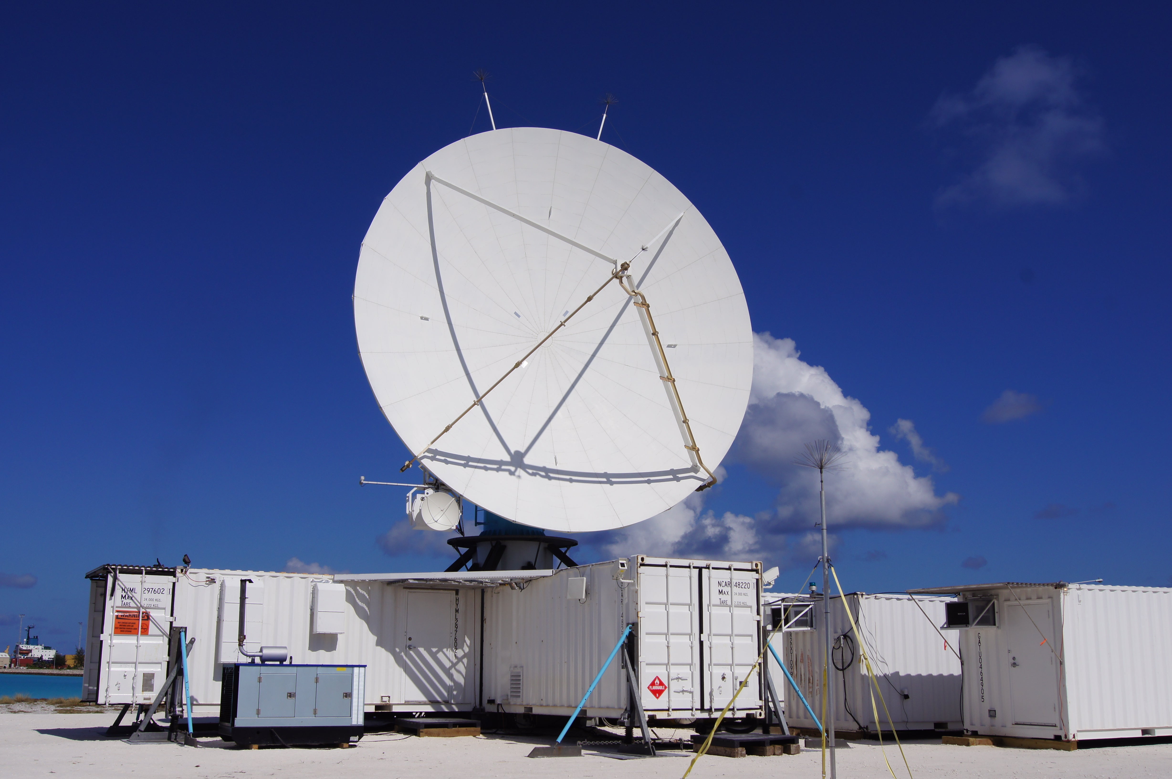
It appears to me that if one wants to make progress in mathematics, one should study the masters and not the pupils. - Niels Henrik Abel.
Nothing is better than reading and gaining more and more knowledge - Stephen William Hawking.
Offline
#2659 2025-12-10 17:04:01
- Jai Ganesh
- Administrator
- Registered: 2005-06-28
- Posts: 53,831
Re: Miscellany
2459) Compass
Gist
A compass is a tool for finding direction. A simple compass is a magnetic needle mounted on a pivot, or short pin. The needle, which can spin freely, always points north. The pivot is attached to a compass card. The compass card is marked with the directions. To use a compass, a person lines up the needle with the marking for north. Then the person can figure out all the other directions.
A compass works because Earth is a huge magnet. A magnet has two main centers of force, called poles—one at each end. Lines of magnetic force connect these poles. Bits of metal near a magnet always arrange themselves along these lines. A compass needle acts like these bits of metal. It points north because it lines up with Earth’s lines of magnetic force.
Earth’s magnetic poles are not the same as the geographic North and South poles. The geographic poles are located at the very top and bottom of a globe. The magnetic poles are nearby but not at exactly the same places. A compass points to the magnetic North Pole, not the geographic North Pole. Therefore, a compass user has to make adjustments to find true north.
A special kind of compass called a gyrocompass does point to true north. The gyrocompass uses a device called a gyroscope, which always points in the same direction. Today large ships carry both magnetic compasses and gyrocompasses.
People in China and Europe first learned how to make magnetic compasses during the 1100s. They discovered that when a magnetized bit of iron floated in water, it pointed north. Sailors soon began to use compasses to navigate, or find their way, at sea.
Summary
A compass, in navigation or surveying, is the primary device for direction-finding on the surface of the Earth. Compasses may operate on magnetic or gyroscopic principles or by determining the direction of the Sun or a star.
The oldest and most familiar type of compass is the magnetic compass, which is used in different forms in aircraft, ships, and land vehicles and by surveyors. Sometime in the 12th century, mariners in China and Europe made the discovery, apparently independently, that a piece of lodestone, a naturally occurring magnetic ore, when floated on a stick in water, tends to align itself so as to point in the direction of the polestar. This discovery was presumably quickly followed by a second, that an iron or steel needle touched by a lodestone for long enough also tends to align itself in a north-south direction. From the knowledge of which way is north, of course, any other direction can be found.
The reason magnetic compasses work as they do is that the Earth itself acts as an enormous bar magnet with a north-south field that causes freely moving magnets to take on the same orientation. The direction of the Earth’s magnetic field is not quite parallel to the north-south axis of the globe, but it is close enough to make an uncorrected compass a reasonably good guide. The inaccuracy, known as variation (or declination), varies in magnitude from point to point upon the Earth. The deflection of a compass needle due to local magnetic influences is called deviation.
Over the centuries a number of technical improvements have been made in the magnetic compass. Many of these were pioneered by the English, whose large empire was kept together by naval power and who hence relied heavily upon navigational devices. By the 13th century the compass needle had been mounted upon a pin standing on the bottom of the compass bowl. At first only north and south were marked on the bowl, but then the other 30 principal points of direction were filled in. A card with the points painted on it was mounted directly under the needle, permitting navigators to read their direction from the top of the card. The bowl itself was subsequently hung on gimbals (rings on the side that let it swing freely), ensuring that the card would always be level. In the 17th century the needle itself took the shape of a parallelogram, which was easier to mount than a thin needle.
During the 15th century navigators began to understand that compass needles do not point directly to the North Pole but rather to some nearby point; in Europe, compass needles pointed slightly east of true north. To counteract this difficulty, British navigators adopted conventional meridional compasses, in which the north on the compass card and the “needle north” were the same when the ship passed a point in Cornwall, England. (The magnetic poles, however, wander in a predictable manner—in more recent centuries Europeans have found magnetic north to be west of true north—and this must be considered for navigation.)
In 1745 Gowin Knight, an English inventor, developed a method of magnetizing steel in such a way that it would retain its magnetization for long periods of time; his improved compass needle was bar-shaped and large enough to bear a cap by which it could be mounted on its pivot. The Knight compass was widely used.
Some early compasses did not have water in the bowl and were known as dry-card compasses; their readings were easily disturbed by shocks and vibration. Although they were less affected by shock, liquid-filled compasses were plagued by leaks and were difficult to repair when the pivot became worn. Neither the liquid nor the dry-card type was decisively advantageous until 1862, when the first liquid compass was made with a float on the card that took most of the weight off the pivot. A system of bellows was invented to expand and contract with the liquid, preventing most leaks. With these improvements liquid compasses made dry-card compasses obsolete by the end of the 19th century.
Modern mariners’ compasses are usually mounted in binnacles, cylindrical pedestals with provision for illuminating the compass face from below. Each binnacle contains specially placed magnets and pieces of steel that cancel the magnetic effects of the metal of the ship. Much the same kind of device is used aboard aircraft, except that, in addition, it contains a corrective mechanism for the errors induced in magnetic compasses when airplanes suddenly change course. The corrective mechanism is a gyroscope, which has the property of resisting efforts to change its axis of spin. This system is called a gyromagnetic compass.
Gyroscopes are also employed in a type of nonmagnetic compass called the gyrocompass. The gyroscope is mounted in three sets of concentric rings connected by gimbals, each ring spinning freely. When the initial axis of spin of the central gyroscope is set to point to true north, it will continue to do so and will resist efforts to realign it in any other direction; the gyroscope itself thus functions as a compass. If it begins to precess (wobble), a pendulum weight pulls it back into line. Gyrocompasses are generally used in navigation systems because they can be set to point to true north rather than to magnetic north.
Details
A compass is a device that shows the cardinal directions used for navigation and geographic orientation. It typically consists of a magnetized needle or another element, such as a compass card or compass rose, that pivots to align itself with magnetic north. Other methods may be used, including gyroscopes, magnetometers, and GPS receivers.
Compasses often show angles in degrees: north corresponds to 0°, and the angles increase clockwise, so east is 90°, south is 180°, and west is 270°. These numbers allow the compass to show azimuths or bearings which are commonly stated in degrees. If local variation between magnetic north and true north is known, then direction of magnetic north also gives direction of true north.
Among the Four Great Inventions, the magnetic compass was first invented as a device for divination as early as the Chinese Han dynasty (since c. 206 BC), and later adopted for navigation by the Song dynasty Chinese during the 11th century. The first usage of a compass recorded in Western Europe and the Islamic world occurred around 1190.
The magnetic compass is the most familiar compass type. It functions as a pointer to "magnetic north", the local magnetic meridian, because the magnetized needle at its heart aligns itself with the horizontal component of the Earth's magnetic field. The magnetic field exerts a torque on the needle, pulling the North end or pole of the needle approximately toward the Earth's North magnetic pole, and pulling the other toward the Earth's South magnetic pole. The needle is mounted on a low-friction pivot point, in better compasses a jewel bearing, so it can turn easily. When the compass is held level, the needle turns until, after a few seconds to allow oscillations to die out, it settles into its equilibrium orientation.
In navigation, directions on maps are usually expressed with reference to geographical or true north, the direction toward the Geographical North Pole, the rotation axis of the Earth. Depending on where the compass is located on the surface of the Earth the angle between true north and magnetic north, called magnetic declination can vary widely with geographic location. The local magnetic declination is given on most maps, to allow the map to be oriented with a compass parallel to true north. The locations of the Earth's magnetic poles slowly change with time, which is referred to as geomagnetic secular variation. The effect of this means a map with the latest declination information should be used. Some magnetic compasses include means to manually compensate for the magnetic declination, so that the compass shows true directions.
Additional Information
A compass is a device that indicates direction. It is one of the most important instruments for navigation.
A compass is a device that indicates direction. It is one of the most important instruments used for navigation. Magnetic compasses are the best-known type of compass. While the design and construction of the magnetic compass have changed significantly over the centuries, the concept of how it works remains the same. A magnetic compass consists of a magnetized needle that rotates to line up with Earth's magnetic field. The ends point to what are known as the north magnetic pole and the south magnetic pole.
History of Compasses
The principle of magnetism has been observed by humans for thousands of years. Ancient Greeks observed the principle of magnetism, but they did not understand its relationship to the Earth or that a magnetized metal would point north. People in Ancient China also recognized magnetism. They learned that a magnetized bar of lodestone tied to a string would always point in the same direction. This observation became part of their spiritual beliefs as religious leaders used a magnetic spoon balanced on a plate to predict the future. Some consider this to be the earliest form of a compass, although compasses are more accurately defined as instruments devised for navigational purposes. A unique aspect of these early compasses in China is that they were oriented to the south and were referred to as “south pointing spoons” or “south pointers.” Later Chinese compasses were similarly oriented to point south rather than north like today’s compasses.
There is evidence that explorers from China and Europe were using compasses to navigate the seas as far back as the 1100s. In fact, many historians believe that people in China were using compasses to navigate long before that time. Miners in search of jade, for instance, appear to have used “south pointing spoons.” Some historians also believe that compasses originated in China and traveled to Europe through trade routes, but others think that Europeans developed the technology independently.
Early Compasses
Very early compasses were made of a magnetized needle attached to a piece of wood or cork that floated freely in a dish of water. As the needle settled, the marked end would point toward magnetic north.
As engineers and scientists learned more about magnetism, the compass needle was mounted and placed in the middle of a card that showed the cardinal directions: north, south, east, and west. In time, 32 points of direction were added to the compass card.
In their earliest use, compasses were likely used as a backup navigational tool for when the sun, stars, or other landmarks could not be seen. As compasses became more reliable and more explorers understood how to use them, compasses became an essential tool for travelers.
Adjustments and Adaptations
By the 15th century, explorers realized that the “north” indicated by a compass needle was not the same as Earth’s true geographic north. This discrepancy between magnetic north and true north is called variation (by mariners or pilots) or magnetic declination (by land navigators), and it varies depending on location. Because of this variation, a compass could lead a novice user many kilometers off-course. Navigators learn to adjust their compass readings to account for variation.
Other adaptations have been made to magnetic compasses over time, especially for their use in marine navigation. When ships evolved from being made of wood to being made of iron and steel, the magnetism of the ship affected compass readings. This difference is called deviation. Adjustments, such as placing soft iron balls (called Kelvin spheres) and bar magnets (called Flinders bars) near the compass, help increase the accuracy of the readings. Deviation must also be taken into account on aircraft using compasses, due to the metal in the construction of an airplane.
Magnetic compasses come in many forms. The most basic are portable compasses for use on casual hikes. Magnetic compasses can have additional features, such as magnifiers for use with maps, a prism or mirror that allows the user to see the landscape and compass reading at the same time, or markings in Braille for people with a visual impairment. The most complicated compasses are complex devices on ships or planes that can calculate and adjust for motion, variation, and deviation.
Other Types of Compasses
Some compasses do not use Earth’s magnetism to indicate direction. The gyrocompass, invented in the early 20th century, uses a spinning gyroscope to follow Earth’s axis of rotation to point to true north. Since magnetic north is not measured, variation is not an issue. Once the gyroscope begins spinning, motion will not disturb it. This type of compass is often used on ships and aircraft.
A solar compass uses the sun as a navigational tool. It was used in the 19thand 20thcenturies to survey land. Because a solar compass is not affected by iron metal deposits or location relative to the poles, a solar compass can be more accurate than a magnetic compass, particularly near the poles. The most common method is to use a compass card and the angle of the shadow of the sun to indicate direction.
Another type of solar compass is an old-fashioned analog (not digital) watch. Using the watch’s hands and the position of the sun, it is possible to determine north or south. Simply hold the watch parallel to the ground (in your hand) and point the 12 o'clock mark in the direction of the sun. Find the angle between the hour hand and the 12 o’clock mark. This is the north-south line. In the Southern Hemisphere, north will be the direction closer to the sun. In the Northern Hemisphere, north will be the direction further from the sun.
Receivers from the global positioning system (GPS) have begun to take the place of compasses. A GPS receiver coordinates with satellites orbiting Earth and monitoring stations on Earth to pinpoint the receiver's location. GPS receivers can plot latitude, longitude, and altitude on a map. In open areas and optimal conditions, standard GPS is accurate to about 6 meters (20 feet), and researchers have developed a so-called “SuperGPS” that is accurate within 10 centimeters (3.9 inches).
Many people throughout history have used knowledge of the stars and constellations as a kind of compass. For example, Polynesians have been using patterns in the sky to navigate the ocean for at least 2,000 years. A native Hawaiian historian, Charles Nainoa Thompson, developed a Hawaiian star compass in the mid-2000s to illustrate how Polynesians use the constellations for navigation. Much like a magnetic compass, there are 32 stars situated around a center point on a star compass.
Impact of the Compass
The compass had a major impact on the world, particularly for people who were navigating the sea. Because compasses were more accurate than other naval navigational tools, explorers used them to explore parts of the world that were unknown to them during the so-called Age of Exploration that began in the early 15th century, a development with both positive and negative impacts. European exploration contributed to trade and the circulation of knowledge, but it would also lead to the spread of disease, the colonization of new lands, and the enslavement of Africans and other indigenous populations. Because today’s global relationships have emerged from these relationships, the legacy of colonization—and the invention of the compass—continues to have a profound impact on the world today.
It appears to me that if one wants to make progress in mathematics, one should study the masters and not the pupils. - Niels Henrik Abel.
Nothing is better than reading and gaining more and more knowledge - Stephen William Hawking.
Offline
#2660 2025-12-11 22:35:59
- Jai Ganesh
- Administrator
- Registered: 2005-06-28
- Posts: 53,831
Re: Miscellany
2460) Indian Elephant
Gist
Indian elephants are smaller than their African relatives but are still among the largest land animals on earth. They have a rounded head, smaller ears, and a long trunk used for feeding, drinking, and even social gestures.
Indian elephants are a subspecies of Asian elephants native to the Indian subcontinent that represent around 60% of all Asian elephants. They are highly intelligent animals with complex social structures that display emotional intelligence.
Summary
Indian elephants may spend up to 19 hours a day feeding and they can produce about 220 pounds of dung per day while wandering over an area that can cover up to 125 square miles. This helps to disperse germinating seeds. They feed mainly on grasses, but large amounts of tree bark, roots, leaves, and small stems are also eaten. Cultivated crops such as bananas, rice, and sugarcane are favored foods as well. Since they need to drink at least once a day, these elephants are always close to a source of fresh water.
Indian elephants are a subspecies of Asian elephants native to the Indian subcontinent that represent around 60% of all Asian elephants. They are highly intelligent animals with complex social structures that display emotional intelligence. The females live in tight-knit family groups led by elderly matriarchs, while males typically live alone.
Indian elephants are similar to their Asian elephant cousins, the Sumatran and Sri Lankan elephants, but are distinguishable from their African cousins by their smaller, more rounded ears and their smaller bodies. Mature Indian elephants are two to three metres (6.6 to 9.8 feet) tall at the shoulders and weigh anywhere from 2,000 to 5,000 kilograms (2.25 to 5.5 tonnes), making them up to one metre smaller and 3,000 kilograms lighter than their African counterparts. Indian elephants also have thinner skin and less hair.
Indian elephants are herbivores and spend up to 19 hours a day eating as much as 136 kilograms (300 pounds) of fruit, grasses, roots, and bark. They are migratory animals with large home ranges, meaning they wander across their forest habitat searching for food, water, and mates.
These habits make them a keystone species—one on which other animals rely for their survival—as they disperse seeds through their faeces and promote vegetation growth by creating clearings and trails that allow more light to reach the forest floor. In short, they play a vital role in the ecosystems in which they live, helping to maintain the biodiversity and ecological health of these regions. However, due to threats like habitat loss and poaching, Indian elephant populations are declining rapidly.
What is an Indian elephant's scientific name?
The scientific name for the Indian elephant is Elephas maximus indicus, roughly translating to ‘greatest elephant from India’. It is one of three subspecies of Asian elephants, the two other being the Sumatran and Sri Lankan elephants, known scientifically as Elephas maximus sumatrensis and Elephas maximus maximus.
Are Indian elephants endangered?
The IUCN Red List has listed Indian elephants as endangered since 1986 because their population and the quality of their habitat are in decline. The number of Asian elephants overall has decreased by 50% over the last three generations, while the population size of Indian elephants has decreased by 11% in just 30 years. These large mammals face human-caused threats, including habitat loss and fragmentation, as well as poaching and human-animal conflict.
Where do Indian elephants live?
Indian elephants are the only Asian elephants that live in mainland Asia. Here, they inhabit a range of different habitats, including dry-thorn forests, moist and dry deciduous forests, tropical evergreen and semi-evergreen forests, as well as cultivated and secondary forests.
They migrate throughout the year in search of vegetation and water, though they do have home ranges too. The size of a range varies based on the number of elephants in the area, as well as the quality and availability of food.
Details
The Indian elephant (Elephas maximus indicus) is one of three extant recognized subspecies of the Asian elephant, native to mainland Asia. The species is smaller than the African elephant species with a convex back and the highest body point on its head. The species exhibits significant sexual dimorphism with a male reaching an average shoulder height of about 2.75 m (9 ft 0 in) and weighing 4,000 kg (8,800 lb) whereas a female reaches an average shoulder height of about 2.4 m (7 ft 10 in) and weighs 2,700 kg (6,000 lb). It has a broader skull with a concave forehead, two large laterally folded ears and a large trunk. It has smooth grey skin with four large legs and a long tail.
The Indian elephant is native to mainland Asia with nearly three-fourth of the population found in India. The species is also found in other countries of the Indian subcontinent including Nepal, Bangladesh, Bhutan, Myanmar and South East Asian countries including Thailand, Malaysia, Laos, Cambodia, and Vietnam with small populations in China. It inhabits grasslands, dry deciduous, moist deciduous, evergreen and semi-evergreen forests across the range. The species is classified as a megaherbivore and consume up to 150 kg (330 lb) of plant matter per day. They consume a variety of diet depending on the habitat and seasons and might include leaves and twigs of fresh foliage, thorn-bearing shoots, flowering plants, fruits and grass.
Since 1986, the Asian elephant has been listed as Endangered on the IUCN Red List as the wild population has declined by at least 50% over the last three elephant generations. The species is threatened by environmental degradation, habitat loss and fragmentation. Poaching of elephants for ivory is a serious threat in some parts of Asia. Project Elephant was launched in 1992 by the Government of India to protect elephant habitats and population.
The Indian elephant is a cultural symbol throughout its range and appears in various religious traditions and mythologies. The elephants are treated positively and is revered as a form of Ganesha in Hinduism. It has been designated the national heritage animal in India and is the national animal of Thailand and Laos.
Taxonomy
The Indian elephant (Elephas maximus indicus) is one of three extant recognized subspecies of the Asian elephant. Carl Linnaeus proposed the scientific name Elephas maximus in 1758 for an elephant from Ceylon. Elephas indicus was proposed by Georges Cuvier in 1798, who described an elephant from India. Frederick Nutter Chasen classified all three as subspecies of the Asian elephant in 1940.
Description
In general, the Asian elephant is smaller than African elephant. Its back is convex or level with the highest body point on its head. The species exhibits significant sexual dimorphism with a male reaching an average shoulder height of about 2.75 m (9 ft 0 in) and weighing up to 4,000 kg (8,800 lb) whereas a female reaches an average shoulder height of about 2.4 m (7 ft 10 in) and weighs up to 2,700 kg (6,000 lb), with specimens rarely exceeding 3.2 m (10 ft) and 5,400 kg (11,900 lb) in males and 2.54 m (8 ft 4 in) 4,160 kg (9,170 lb) in females. The largest Indian elephant was 3.43 m (11.3 ft) high at the shoulder. On average, it measures 5.5–6.5 m (18–21 ft) in length including the trunk.
It has a broader skull with a concave forehead and two dorsal bulges on the top. Two large laterally folded ears and a large trunk with one finger-like process are attached to the head. It has 20 pairs of ribs and 34 vertebrae. There are four large legs which are almost straight with broader toes and with five nail like structures on each foreleg and four on each of the hind-legs. The large legs help support the larger weight for longer periods without spending much energy with the broad feet helping to cushion against hard surfaces. It has a long tail measuring on average 1.2–1.5 m (3 ft 11 in – 4 ft 11 in) in length. The skin color is generally grey and lighter than that of E. m. maximus but darker than that of E. m. sumatranus. The skin is generally smoother than that of the African species and might consist of smaller patches of white depigmentation or grey spots. The body is covered by brownish to reddish hairs which reduce and darken with age. The female is usually smaller than the male with short or no tusks. There are about 29 narrow cheek teeth.
Additional Information
The Indian elephant (Elephas maximus indicus) is one of the most respected animals in India. For centuries, it has been a part of our culture, mythology, and daily life. Worshipped as a symbol of strength and wisdom, elephants are seen in temples, festivals, and folklore across the country. But beyond culture, they also play a vital role in the forests dispersing seeds, clearing vegetation, and helping new life grow.
How to Identify an Indian Elephant
Indian elephants are smaller than their African relatives but are still among the largest land animals on earth. They have a rounded head, smaller ears, and a long trunk used for feeding, drinking, and even social gestures. Unlike African elephants, where both males and females grow tusks, in India only some males have tusks. The tuskless males and females are called makhnas.
Size, Weight, and Appearance
Adult males: 8-10 feet tall at the shoulder, weighing 2,000-5,000 kg
Females: 7-9 feet tall, slightly smaller than males
Skin: Dark grey to dusty brown, often covered with mud or dust (nature’s sunscreen)
These gentle giants love dust baths, which not only keep them cool but also protect them from insect bites.
Birth and Life Cycle
Elephants have one of the longest pregnancies of any land animal about 22 months. A calf weighs close to 100 kg at birth and is cared for by the entire herd. These social bonds are strong, and young elephants rarely leave the safety of their mothers and aunts.
In the wild, Indian elephants can live 60-70 years. In captivity, their lifespan often depends on how well they are cared for.
Key Characteristics of Indian Elephant
Feature : Description
Scientific Name : Elephas maximus indicus
Height : 2 to 3.5 m (6.6 to 11.5 ft) at the shoulder
Weight : 2,000 to 5,500 kg (4,400 to 12,100 lbs)
Lifespan : 60 to 70 years in the wild
Habitat : Grasslands, dry deciduous, moist deciduous, evergreen, and semi-evergreen forests.
Distribution : Found in India and other countries of mainland Asia, including Nepal, Bangladesh, Bhutan, Myanmar, Thailand, and others.
Diet : Herbivore. Consumes up to 150 kg (330 lbs) of vegetation per day.
Social Structure : Live in matriarchal herds led by the oldest and most experienced female.
Conservation Status : Endangered (IUCN Red List).
What Do They Eat?
An adult elephant can eat over 150 kg of food a day grasses, leaves, bark, and seasonal fruits. They drink more than 100 liters of water daily. Despite their bulk, they can run up to 40 km/h if threatened.
Where Do Indian Elephants Live?
Indian elephants prefer dense forests, grasslands, and river valleys. They never stray far from water.
Main Elephant Regions in India
Southern India – Karnataka, Kerala, Tamil Nadu
Central India – Chhattisgarh, Jharkhand, Odisha
Northeast India – Assam, Arunachal Pradesh, Meghalaya
Northern India – Uttarakhand, Uttar Pradesh
Together, these regions form the last strongholds of the Indian elephant, where conservation efforts are vital to keep their ancient migration routes alive.
Best Places to See Elephants in India
Jim Corbett National Park (Uttarakhand) – Famous for large herds crossing forest roads.
Kaziranga National Park (Assam) – Ideal for spotting elephants along with rhinos.
Periyar Wildlife Sanctuary (Kerala) – Known for elephant sightings near the lake.
Bandipur & Nagarhole (Karnataka) – Rich elephant corridors with strong protection.
These parks are also popular for elephant safaris, though ethical wildlife viewing always prefers observing them in the wild, not in captivity.
Migration and Movement Patterns
Indian elephants travel long distances as the seasons change, mainly in search of food and water. Some herds follow the same routes for generations, guided by the memory of matriarchs who know the land well.
Major Elephant Migration Regions in India
Nilgiri Biosphere Reserve (Karnataka, Kerala, Tamil Nadu) – One of the most important elephant landscapes with famous corridors like Mudumalai-Bandipur-Wayanad-Nagarhole.
Kaziranga-Karbi Anglong (Assam) – Elephants move between grasslands and nearby hills depending on the season.
Dooars and North Bengal (West Bengal) – Regular movements between forests of Bhutan foothills and Indian reserves.
Rajaji-Corbett (Uttarakhand) – Known for elephants moving between Shivalik hills and Terai grasslands.
Eastern India (Odisha, Jharkhand, Chhattisgarh) – Seasonal migrations often bring elephants close to farmlands.
Wildlife corridors in these regions are critical, as they connect fragmented forests and reduce conflict. Without them, elephants are forced to cross farms, roads, and railway lines, which increases the risk of accidents and human-elephant conflict.
Behavior and Social Life
Elephants live in matriarch-led herds, usually made up of females and calves. Males leave the group when they mature and either live alone or in small bachelor groups.
Daily Routine
* Foraging for 12-18 hours a day
* Bathing and cooling off in rivers or mud pools
* Walking long distances to find food and water
* Resting and social bonding
Communication
They “talk” through rumbles, trumpets, body language, and even vibrations felt through the ground. Elephants are known to mourn their dead, showing remarkable emotional intelligence.

It appears to me that if one wants to make progress in mathematics, one should study the masters and not the pupils. - Niels Henrik Abel.
Nothing is better than reading and gaining more and more knowledge - Stephen William Hawking.
Offline
#2661 2025-12-12 21:10:56
- Jai Ganesh
- Administrator
- Registered: 2005-06-28
- Posts: 53,831
Re: Miscellany
2461) Andes Mountains
Gist
The Andes Mountains are located along the western coastline of South America. The name Andes stems from the Quechua word anti, which means high crest. The Andes is the world's longest range of mountains and runs north to south along the Pacific Ring of Fire and seven countries from Venezuela to Chile.
The Andes Mountains are not only one of the longest mountain ranges in the world but also the highest range outside of the Himalayas, making them an important natural landmark and a wonderful source of biodiversity for the region.
How cold are the Andes mountains at night?
From 11,500 to 14,800 feet it generally is cold—with great differences between day and night and between sunshine and shadow—and temperatures are below freezing at night. Between about 13,500 and 15,700 feet (the puna), the climate of the páramo is found, with constant subfreezing temperatures.
Summary
The Andes, Andes Mountains or Andean Mountain Range (Spanish: Cordillera de los Andes; Quechua: Anti) are the longest continental mountain range in the world, forming a continuous highland along the western edge of South America. The range is 8,900 km (5,500 mi) long and 200 to 700 km (120 to 430 mi) wide (widest between 18°S and 20°S latitude) and has an average height of about 4,000 m (13,000 ft). The Andes extend from south to north through seven South American countries: Argentina, Chile, Bolivia, Peru, Ecuador, Colombia, and Venezuela.
Along their length, the Andes are split into several ranges, separated by intermediate depressions. The Andes are the location of several high plateaus—some of which host major cities such as Arequipa, Bogotá, Cali, Medellín, El Alto, La Paz, Mérida, Santiago and Sucre. The Altiplano Plateau is the world's second highest after the Tibetan Plateau. These ranges are in turn grouped into three major divisions based on climate: the Tropical Andes, the Dry Andes, and the Wet Andes.
The Andes are the highest mountain range outside of Asia. The range's highest peak, Argentina's Aconcagua, rises to an elevation of about 6,961 m (22,838 ft) above sea level. The peak of Chimborazo in the Ecuadorian Andes is farther from the Earth's center than any other location on the Earth's surface, due to the equatorial bulge resulting from the Earth's rotation. The world's highest volcanoes are in the Andes, including Ojos del Salado on the Chile–Argentina border, which rises to 6,893 m (22,615 ft).
The Andes are also part of the American Cordillera, a chain of mountain ranges (cordillera) that consists of an almost continuous sequence of mountain ranges that form the western "backbone" of the Americas and Antarctica.
Details
Andes Mountains is a mountain system of South America and one of the great natural features on Earth.
The Andes consist of a vast series of extremely high plateaus surmounted by even higher peaks that form an unbroken rampart over a distance of some 5,500 miles (8,900 kilometers)—from the southern tip of South America to the continent’s northernmost coast on the Caribbean. They separate a narrow western coastal area from the rest of the continent, affecting deeply the conditions of life within the ranges themselves and in surrounding areas. The Andes contain the highest peaks in the Western Hemisphere. The highest of them is Mount Aconcagua (22,831 feet [6,959 meters]) on the border of Argentina and Chile (see Researcher’s Note: Height of Mount Aconcagua).
The Andes are not a single line of formidable peaks but rather a succession of parallel and transverse mountain ranges, or cordilleras, and of intervening plateaus and depressions. Distinct eastern and western ranges—respectively named the Cordillera Oriental and the Cordillera Occidental—are characteristic of most of the system. The directional trend of both the cordilleras generally is north-south, but in several places the Cordillera Oriental bulges eastward to form either isolated peninsula-like ranges or such high intermontane plateau regions as the Altiplano (Spanish: “High Plateau”), occupying adjoining parts of Argentina, Chile, Bolivia, and Peru.
Some historians believe the name Andes comes from the Quechuan word anti (“east”); others suggest it is derived from the Quechuan anta (“copper”). It perhaps is more reasonable to ascribe it to the anta of the older Aymara language, which connotes copper color generally.
Physical features
There is no universal agreement about the major north-south subdivisions of the Andes system. For the purposes of this discussion, the system is divided into three broad categories. From south to north these are the Southern Andes, consisting of the Chilean, Fuegian, and Patagonian cordilleras; the Central Andes, including the Peruvian cordilleras; and the Northern Andes, encompassing the Ecuadorian, Colombian, and Venezuelan (or Caribbean) cordilleras.
Geology
The Andean mountain system is the result of global plate-tectonic forces during the Cenozoic Era (roughly the past 65 million years) that built upon earlier geologic activity. About 250 million years ago the crustal plates constituting the Earth’s landmass were joined together into the supercontinent Pangaea. The subsequent breakup of Pangaea and of its southern portion, Gondwana, dispersed these plates outward, where they began to take the form and position of the present-day continents. The collision (or convergence) of two of these plates—the continental South American Plate and the oceanic Nazca Plate—gave rise to the orogenic (mountain-building) activity that produced the Andes.
Many of the rocks comprising the present-day cordilleras are of great age. They began as sediments eroded from the Amazonia craton (or Brazilian shield)—the ancient granitic continental fragment that constitutes much of Brazil—and deposited between about 450 and 250 million years ago on the craton’s western flank. The weight of these deposits forced a subsidence (downwarping) of the crust, and the resulting pressure and heat metamorphosed the deposits into more resistant rocks; thus, sandstone, siltstone, and limestone were transformed, respectively, into quartzite, shale, and marble.
Approximately 170 million years ago this complex geologic matrix began to be uplifted as the eastern edge of the Nazca Plate was forced under the western edge of the South American Plate (i.e., the Nazca Plate was subducted), the result of the latter plate’s westward movement in response to the opening of the Atlantic Ocean to the east. This subduction-uplift process was accompanied by the intrusion of considerable quantities of magma from the mantle, first in the form of a volcanic arc along the western edge of the South American Plate and later by the injection of hot solutions into surrounding continental rocks; the latter process created numerous dikes and veins containing concentrations of economically valuable minerals that later were to play a critical role in the human occupation of the Andes.
The intensity of this activity increased during the Cenozoic Era, and the present shape of the cordilleras emerged. The accepted time period for their rise had been from about 15 million to 6 million years ago. However, through the use of more advanced techniques, researchers in the early 21st century were able to determine that the uplift started much earlier, about 25 million years ago. The resultant mountain system exhibits an extraordinary vertical differential of more than 40,000 feet between the bottom of the Peru-Chile (Atacama) Trench off the Pacific coast of the continent and the peaks of the high mountains within a horizontal distance of less than 200 miles. The tectonic processes that created the Andes have continued to the present day. The system—part of the larger circum-Pacific volcanic chain that often is called the Ring of Fire—remains volcanically active and is subject to devastating earthquakes.
Physiography of the Southern Andes
The Fuegian Andes begin on the mountainous Estados (Staten) Island, the easternmost point of the Tierra del Fuego archipelago, reaching an elevation of 3,700 feet. They run to the west through Grande Island, where the highest ridges—including Mounts Darwin, Valdivieso, and Sorondo—are all less than 7,900 feet high. The physiography of this southernmost subdivision of the Andes system is complicated by the presence of the independent Sierra de la Costa.
The Patagonian Andes rise north of the Strait of Magellan. Numerous transverse and longitudinal depressions and breaches cut this wild and rugged portion of the Andes, sometimes completely; many ranges are occupied by ice fields, glaciers, rivers, lakes, or fjords. The crests of the mountains exceed 10,000 feet (Mount Fitz Roy reaching 11,073 feet) north to latitude 46° S but average only 6,500–8,400 feet from latitude 46° to 41° S, except for Mount Tronador (11,453 feet). North of Lake Aluminé (Argentina) the axis of the cordillera shifts to the east up to a zone of transition between latitude 37° and 35° S, where the geographic aspect and geomorphic structure change. This zone marks the most commonly accepted northern extent of the Patagonian Andes; there is some disagreement, however, about this limit, some placing it farther south, at the Gulf of Penas, (47° S) and others considering it to be to the north, around 30° S.
The line of permanent snow becomes higher in elevation with decreasing latitude in the Southern Andes: 2,300 feet in Tierra del Fuego, 5,000 feet at Osorno Volcano (41° S), and 12,000 feet at Domuyo Volcano (36°38′ S). A line of active volcanoes—including Yate, Corcovado, and Macá—occurs about 40° to 46° S; the southernmost of these, Mount Hudson of Chile, erupted in 1991. Enormous ice fields are located between Mount Fitz Roy (called Mount Chaltel in Chile) and Lake Buenos Aires (Lake General Carrera in Chile) at both sides of Baker Fjord; the Viedma, Upsala, and other glaciers originate from these fields. Other notable features are the more than 50 lakes found south of 39° S. Those depressions that are free of water form fertile valleys called vegas, which are easily reached by low passes. Magnificent and impenetrable forests grow on both sides of these cordilleras, especially on the western slopes; these forests cover the mountains as high as the snow line, although at the higher altitudes toward the north and in Tierra del Fuego the vegetation is lower and less dense. Both Argentina and Chile have created national parks to preserve the area’s natural beauty.
Physiography of the Central Andes
The Central Andes begin at latitude 35° S, at a point where the cordillera undergoes a sharp change of character. Its width increases to about 50 miles, and it becomes arid and higher; the passes, too, are higher and more difficult to cross. Glaciers are rare and found only at high elevations. The main range serves as the boundary between Chile and Argentina and also is the drainage divide between rivers flowing to the Pacific and the Atlantic. The last of the southern series of volcanoes, Mount Tupungato (21,555 feet) is just east of Santiago, Chile. A line of lofty, snowcapped peaks rise between Tupungato and the mighty Mount Aconcagua. To the north of Aconcagua lies Mount Mercedario (22,211 feet), and between them are the high passes of Mount Espinacito (16,000 feet) and Mount Patos (12,825 feet). South of Anconcagua the passes include Pircas (16,960 feet), Bermejo (more than 10,000 feet), and Iglesia (13,400 feet). Farther north the passes are more numerous but higher. The peaks of Mounts Bonete, Ojos del Salado, and Pissis surpass 20,000 feet.
The peak of Tres Cruces (22,156 feet) at 27° S latitude marks the culmination of this part of the cordillera. To the north is found a transverse depression and the southern limit of the high plateau region called the Atacama Plateau in Argentina and Chile and the Altiplano in Bolivia and Peru. The cordillera grows wider as it advances into Bolivia and Peru, where the great plateau is bounded by two ranges: the Occidental and the Oriental.
Northward, to latitude 18° S, the peaks of El Cóndor, Sierra Nevada, Llullaillaco, Galán, and Antofalla all exceed 19,000 feet. The two main ranges and several volcanic secondary chains enclose depressions called salars because of the deposits of salts they contain; in northwestern Argentina, the Sierra de Calalaste encompasses the large Antofalla Salt Flat. Volcanoes of this zone occur mostly on a northerly line along the Cordillera Occidental as far as Misti Volcano (latitude 16° S) in Peru.
The western slopes of the Cordillera Occidental descend gradually to the Atacama Desert along the coast. At about 18° S the trend of the Cordillera Occidental changes to a northwesterly direction. The Cordillera Oriental to the east, lower and built on a broad bed of lava, is cut and denuded by rivers with steep gradients, fed by heavy rainfall. It has two sections. The southern portion is 150 miles wide and—with the exception of Chorolque Peak in Bolivia (18,414 feet)—of relatively low elevation. The northern section in Bolivia, called Cordillera Real, is narrow, with higher peaks and glaciers; the most important peaks, at over 21,000 feet, are Mounts Illimani and Illampu.
At about latitude 22° S the Cordillera Oriental penetrates into Bolivia and describes a wide semicircle to the north and then to the northwest; to the west the Altiplano reaches its broadest extent. The Altiplano—500 miles long and 80 miles wide—is one of the largest interior basins of the world. Varying in elevation from 11,200 to 12,800 feet, it has no drainage outlet to the ocean. Roughly in the center of the plateau is a great depression between the two cordilleras. Lake Titicaca, the highest navigable lake of the world (110 miles long), fills the northern part of the depression; the Desaguadero River flows south through the depression, draining Titicaca water into the smaller Lake Poopó.
As the Andes enter Peru, the Cordillera Occidental runs parallel to the coast, while the Cordillera Real from Bolivia ends in the rough mountain mass of the Vilcanota Knot at latitude 15° S. From this knot (nudo), two lofty and narrow chains emerge northward, the Cordilleras de Carabaya and Vilcanota, separated by a deep gorge; a third range, the Cordillera de Vilcabamba, appears to the west of these and northwest of the city of Cuzco. The three ranges are products of erosive action of rivers that have cut deep canyons between them. West of the Cordillera de Vilcabamba, the Apurímac River runs in one of the deepest canyons of the Western Hemisphere. The city of Cuzco lies in the valley west of the Cordillera de Vilcanota at an altitude of nearly 11,000 feet.
The Peruvian Andes traditionally have been described as three cordilleras, which come together at the Vilcanota, Pasco, and Loja (Ecuador) knots. The Pasco Knot is a large, high plateau. To the west it is bounded by the Cordillera Huarochirí, on the west slope of which the Rímac River rises in a cluster of lakes fed by glaciers and descends rapidly to the ocean (15,700 feet in 60 miles). Ticlio Pass, at an altitude of some 15,800 feet, is used by a railway. Many small lakes and ponds are found on the knots, with Lake Junín (about 20 miles long) being the largest.
North of the Pasco Knot, three different ranges run along the plateau: the Cordilleras Occidental, Central, and Oriental. In the Cordillera Occidental, at latitude 10° S, the deep, narrow Huaylas Valley separates two ranges, Cordillera Blanca to the east and Cordillera Negra to the west; the Santa River runs between them and cuts Cordillera Negra to drain into the Pacific. Cordillera Blanca is a complex highland with permanently snowcapped peaks, some among the highest of the Andes (e.g., Mount Huascarán, at 22,205 feet). At times, the glaciers that rise there are broken off by earthquakes and rush down the slopes, demolishing vegetation and settlements in their paths. Cordillera Negra, so named because it is not covered with snow, is lower.
The two ranges join together at latitude 9° S. The Marañón River, which runs northward between the Cordilleras Occidental and Central at about 6° S, changes its direction of flow to the northeast, penetrating into a region of narrow transverse water gaps (pongos) that cut the cordillera to reach the Amazon basin. These include Rentema (about one and one-fourth miles long and 200 feet wide), Mayo, Mayasito, and Huarcaya gaps and—the most important—Manseriche Gap, which is seven miles long.
Between the Cordilleras Central and Oriental, the Huallaga River runs in a deep gorge with few small valleys; it cuts the eastern cordillera at Aguirre Gap (latitude 6° S). The Cordillera Oriental ends in the Amazon basin at 5° S.
The permanent snow line reaches an altitude of 19,000 feet in Mount Chanchani (about latitude 16° S) and declines to about 15,000 feet in Cordillera Blanca and to 13,000 feet on Mount Huascarán. Permanent snow is less common north of 8° S, the puna grasslands end, and the so-called humid puna, or jalca, begins. Mountains become wider and smoother in appearance, while vegetation changes to heathland and trees. The altitude diminishes, and passes are much lower, as at Porculla Pass (7,000 feet) east of Piura.
Physiography of the Northern Andes
A rough and eroded high mass of mountains called the Loja Knot (4° S) in southern Ecuador marks the transition between the Peruvian cordilleras and the Ecuadorian Andes. The Ecuadorian system consists of a long, narrow plateau running from south to north bordered by two mountain chains containing numerous high volcanoes. To the west, in the geologically recent and relatively low Cordillera Occidental, stands a line of 19 volcanoes, 7 of them exceeding 15,000 feet in elevation. The eastern border is the higher and older Cordillera Central, capped by a line of 20 volcanoes; some of these, such as Chimborazu Volcano (20,702 feet), have permanent snowcaps.
The outpouring of lava from these volcanoes has divided the central plateau into 10 major basins that are strung in beadlike fashion between the two cordilleras. These basins and their adjacent slopes, which are intensively cultivated, contain roughly half of Ecuador’s population.
A third cordillera has been identified in the eastern jungle of Ecuador and has been named the Cordillera Oriental. The range appears to be an ancient alluvial formation that has been divided by rivers and heavy rainfall into a number of mountain masses. Such masses as the cordilleras of Guacamayo, Galeras, and Lumbaquí are isolated or form irregular short chains and are covered by luxuriant forest. Altitudes do not exceed 7,900 feet, except at Cordilleras del Cóndor (13,000 feet) and Mount Pax (11,000 feet).
North of the boundary with Colombia is a group of high, snowcapped volcanoes (Azufral, Cumbal, Chiles) known as the Huaca Knot. Farther to the north is the great massif of the Pasto Mountains (latitude 1°–2° N), which is the most important Colombian physiographic complex and the source of many of the country’s rivers.
Three distinct ranges, the Cordilleras Occidental, Central, and Oriental, run northward. The Cordillera Occidental, parallel to the coast and moderately high, reaches an elevation of nearly 13,000 feet at Mount Paramillo before descending in three smaller ranges into the lowlands of northern Colombia. The Cordillera Central is the highest (average altitude of almost 10,000 feet) but also the shortest range of Colombian Andes, stretching some 400 miles before its most northerly spurs disappear at about latitude 8° N. Most of the volcanoes of the zone are in this range, including Mounts Tolima (17,105 feet), Ruiz (17,717 feet), and Huila (18,865 feet). At about latitude 6° N, the range widens into a plateau on which Medellín is situated.
Between the Cordilleras Central and Occidental is a great depression, the Patía-Cauca valley, divided into three longitudinal plains. The southernmost is the narrow valley of the Patía River, the waters of which flow to the Pacific. The middle plain is the highest in elevation (8,200 feet) and constitutes the divide of the other two. The northern plain, the largest (15 miles wide and 125 miles long), is the valley of Cauca River, which drains northward to the Magdalena River.
The Cordillera Oriental trends slightly to the northeast and is the widest and the longest of the three. The average altitude is 7,900 to 8,900 feet. North of latitude 3° N the cordillera widens and after a small depression rises into the Sumapaz Uplands, which range in elevation from 10,000 to 13,000 feet. North of the Sumapaz Upland the range divides into two, enclosing a large plain 125 miles wide and 200 miles long, often interrupted by small transverse chains that form several upland basins called sabanas that contain about a third of Colombia’s population. The city of Bogotá is on the largest and most populated of these sabanas; other important cities on sabanas are Chiquinquirá, Tunja, and Sogamoso. East of Honda (5° N) the cordillera divides into a series of abrupt parallel chains running to the north-northeast; among them the Sierra Nevada del Cocuy (18,022 feet) is high enough to have snowcapped peaks.
Farther north the central ranges of the Cordillera Central come to an end, but the flanking chains continue and diverge to the north and northeast. The westernmost of these chains is the Sierra de Ocaña, which on its northeastern side includes the Sierra de Perijá; the latter range forms a portion of the boundary between Colombia and Venezuela and extends as far north as latitude 11° N in La Guajira Peninsula. The eastern chain bends to the east and enters Venezuela as the Cordillera de Mérida. On the Caribbean coast just west of the Sierra de Perijá stands the isolated, triangular Santa Marta Massif, which rises abruptly from the coast to snowcapped peaks of 18,947 feet; geologically, however, the Santa Marta Massif is not part of the Andes.
The Venezuelan Andes are represented by the Cordillera de Mérida (280 miles long, 50 to 90 miles wide, and about 10,000 feet in elevation), which extends in a northeasterly direction to the city of Barquisimeto, where it ends. The cordillera is a great uplifted axis where erosion has uncovered granite and gneiss rocks but where the northwestern and southeastern flanks remain covered by sediments; it consists of numerous chains with snow-covered summits separated by longitudinal and transverse depressions—Sierras Tovar, Nevada, Santo Domingo, de la Culata, Trujillo, and others. The range forms the northwestern limit of the Orinoco River basin, beyond which water flows to the Caribbean. North of Barquisimeto, the Sierra Falcón and Cordillera del Litoral (called in Venezuela the Sistema Andino) do not belong to the Andes but rather to the Guiana system.
Additional Information
The Andes Mountains are such a fascinating and important part of South America’s geography and history. They are home to a unique ecosystem, rich in mineral resources, and provide freshwater for millions of people.
Flora and Fauna in The Andes Mountains
The Andes Mountains are also home to a wide variety of animal species, many of which are found nowhere else in the world.
Due to the altitude range of the Andes, from sea level to over 6,900 meters, the animal species found in the mountains are adapted to different climates and environments. Here are some of the most notable animal species that can be found in the Andes Mountains:
1. Vicuña
The Vicuña is a relative of the llama and is found in the high Andes Mountains of Peru, Chile, Bolivia, and Argentina. They are known for their fine wool, which is used to make high-quality clothing.
2. Andean Condor
The Andean Condor is one of the largest flying birds in the world and can be found throughout the Andes Mountains. They are scavengers and feed on carrion.
3. Spectacled Bear
The Spectacled Bear is the only bear species found in South America, and they are native to the Andes Mountains. They are named for the light-colored fur around their eyes that gives the appearance of wearing spectacles.
4. Puma
The Puma, also known as the mountain lion or cougar, is a large carnivorous cat found throughout the Andes Mountains. They are solitary animals and hunt prey such as deer, guanacos, and vicuñas.
5. Andean Cat
The Andean Cat is a small wild cat found in the high Andes Mountains of Bolivia, Peru, Chile, and Argentina. They are one of the rarest cat species in the world and are listed as endangered.
6. Chinchilla
The Chinchilla is a small rodent found in the Andes Mountains of Peru, Chile, Bolivia, and Argentina. They are known for their soft, dense fur, which is used for clothing and accessories.
7. Andean math-of-the-rock
The Andean math-of-the-rock is a brightly colored bird that is found in the cloud forests of the Andes Mountains. They are known for their bright red feathers.
8. Alpaca
The Alpaca is a domesticated camelid that is found throughout the Andes Mountains. They are bred for their wool, which is used to make clothing, blankets, and other textiles.
9. Giant Otter
The Giant Otter is the largest otter species in the world and can be found in the rivers and lakes of the Andes Mountains. They are highly social and live in family groups.
10, Mountain Viscacha
The Mountain Viscacha is a rodent found in the high Andes Mountains of Peru, Chile, Bolivia, and Argentina. They are known for their long, bushy tails and are sometimes called “Andean rabbits” due to their resemblance to rabbits.
Many of these incredible species are adapted to the unique environment of the Andes, and some are found nowhere else in the world. Protecting the habitats and ecosystems of these animals is crucial for maintaining the biodiversity of the Andes Mountains.
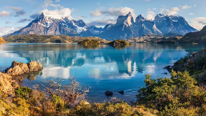
It appears to me that if one wants to make progress in mathematics, one should study the masters and not the pupils. - Niels Henrik Abel.
Nothing is better than reading and gaining more and more knowledge - Stephen William Hawking.
Offline
#2662 2025-12-13 21:13:55
- Jai Ganesh
- Administrator
- Registered: 2005-06-28
- Posts: 53,831
Re: Miscellany
2462) Trans Siberian Railway
Gist
The classic Trans-Siberian Railway runs from Moscow in European Russia to Vladivostok on the Pacific coast, crossing nearly 9,289 kilometers (5,772 miles) and eight time zones, making it the world's longest railway line, with branches extending to destinations like Beijing (Trans-Mongolian) and China (Trans-Manchurian).
The Trans-Siberian Railway, historically known as the Great Siberian Route and often shortened to Transsib, is a large railway system that connects European Russia to the Russian Far East. Spanning a length of over 9,289 kilometers (5,772 miles), it is the longest railway line in the world.
Summary
The Trans-Siberian Railway, historically known as the Great Siberian Route and often shortened to Transsib, is a large railway system that connects European Russia to the Russian Far East. Spanning a length of over 9,289 kilometers (5,772 miles), it is the longest railway line in the world. It runs from the city of Moscow in the west to the city of Vladivostok in the east.
During the period of the Russian Empire, government ministers—personally appointed by Alexander III and his son Nicholas II—supervised the building of the railway network between 1891 and 1916. Even before its completion, the line attracted travelers who documented their experiences. Since 1916, the Trans-Siberian Railway has directly connected Moscow with Vladivostok. As of 2021, expansion projects remain underway, with connections being built to Russia's neighbors Mongolia, China, and North Korea. Additionally, there have been proposals and talks to expand the network to Tokyo, Japan, with new bridges or tunnels that would connect the mainland railway via the Russian island of Sakhalin and the Japanese island of Hokkaido.
Route
The railway is often associated with the main transcontinental Russian line that connects many large and small cities of the European and Asian parts of Russia. At a Moscow–Vladivostok track length of 9,289 kilometers (5,772 miles), it spans a record eight time zones. Taking eight days to complete the journey, it was the third-longest single continuous service in the world, after the Moscow–Pyongyang service 10,267 kilometers (6,380 mi) and the former Kiev–Vladivostok service 11,085 kilometers (6,888 mi), both of which also follow the Trans-Siberian for much of their routes.
The main route begins in Moscow at Yaroslavsky Vokzal, runs through Yaroslavl or Chelyabinsk, Omsk, Novosibirsk, Krasnoyarsk, Irkutsk, Ulan-Ude, Chita, and Khabarovsk to Vladivostok via southern Siberia. A second primary route is the Trans-Manchurian, which coincides with the Trans-Siberian east of Chita as far as Tarskaya (a stop 12 km (7 mi) east of Karymskoye, in Chita Oblast), about 1,000 km (621 mi) east of Lake Baikal. From Tarskaya the Trans-Manchurian heads southeast, via Harbin Harbin–Manzhouli railway and Mudanjiang Harbin–Suifenhe railway in China's Northeastern provinces (from where a connection to Beijing is used by one of the Moscow–Beijing trains), joining the main route in Ussuriysk just north of Vladivostok.
The third primary route is the Trans-Mongolian Railway, which coincides with the Trans-Siberian as far as Ulan-Ude on Lake Baikal's eastern shore. From Ulan-Ude the Trans-Mongolian heads south to Ulaanbaatar before making its way southeast to Beijing. In 1991, a fourth route running further to the north was finally completed, after more than five decades of sporadic work. Known as the Baikal–Amur Mainline (BAM), this recent extension departs from the Trans-Siberian line at Taishet several hundred miles west of Lake Baikal and passes the lake at its northernmost extremity. It crosses the Amur River at Komsomolsk-na-Amure (north of Khabarovsk), and reaches the Tatar Strait at Sovetskaya Gavan.
Details
Trans-Siberian Railroad, the longest single rail system in the world, stretching 5,771 miles (9,288 km) across Russia between Moscow and Vladivostok. If its connection to the port station of Nakhodka is also included, the system reaches a total of 5,867 miles (9,441 km). The Trans-Siberian Railroad has had a profound effect on the region of Siberia as well as great importance in the economic and military history of the Russian Empire and the Soviet Union.
The main track length of the Trans-Siberian Railroad between Moscow and Vladivostok spans eight time zones and involves a journey time of seven days. Its western terminus is the Yaroslavsky station in Moscow, although a connecting service can be used to go farther west to St. Petersburg on the Baltic Sea. Moving eastward from Moscow, the railroad’s main route passes through Yekaterinburg and crosses the Ural Mountains before reaching Novosibirsk on the Ob River and then Krasnoyarsk on the Yenisey River. The route extends through Irkutsk and Ulan-Ude, following the southern shore of Lake Baikal between those cities, and then moves roughly in parallel to Russia’s border with Mongolia and then China before arriving at Khabarovsk on the Amur River and, finally, at Vladivostok on the Sea of Japan (East Sea).
A secondary route of the Trans-Siberian Railroad branches out at Ulan-Ude. For trains traveling eastward, it heads south to Mongolia’s capital, Ulaanbaatar, and onward to Beijing, China. This route is known as the Trans-Mongolian Railroad. A third route, the Trans-Manchurian Railroad, turns southeast after Lake Baikal and goes to the Chinese cities of Harbin and Mudanjiang before rejoining the main track just before Vladivostok. The Trans-Manchurian Railroad also provides service to P’yŏngyang, North Korea.
Throughout its history, Siberia has been subject to particularly harsh winter weather, and efforts to develop the region, beginning with Russian occupation of it during the 16th century, made little progress until well into the 19th century because of the absence of good roads. Horse-drawn sledges were the common mode of transport in winter, and in the summer months river navigation was used. Early attempts to set up a railway in the region were a response to the Russian Empire’s colonization of Siberia. Colonizing forces had to either transport essentials from Russian lands in the west or import them from China and Korea. However, progress on building a railway was slow because of the Russian bureaucracy and because Siberia was not, at the time, considered commercially important enough to invest in new infrastructure.
Russia’s focus during the later 19th century was on Central Asia, which was seen as a buffer zone between the Russian Empire and the British-ruled Indian subcontinent. Both powers engaged in the “Great Game” to consolidate their presence in Central Asia and to influence the many khanates of the region. The British advanced to Afghanistan, while the Russians eventually annexed the khanates of Khiva and Bukhara. Russia built the Trans-Caspian Railroad, which in 1888 reached Samarkand in present-day Uzbekistan, putting Afghanistan at risk of Russian invasion.
Russia’s focus shifted east under the vision of Sergei Witte, who, while working within the Russian ministry of finance, convinced Alexander III in 1891 to begin construction of what would become the Trans-Siberian Railroad. The intent was to extend Russian influence into East Asia and to capture global trade from British hands. The railway would allow merchandise and raw materials to be transported from Europe to the Pacific in half the time it took by sea. It would thus be attractive to traffic by other countries as well, threatening British domination on their traditional sea routes. So, too, the railway would allow the extraction of hitherto untapped resources in Siberia.
Work on the Trans-Siberian Railroad proceeded simultaneously in several sections. It was built concurrently in three stretches. The first stretch was the West Siberian Railroad from Chelyabinsk to the Ob River, completed in 1896. The second stretch, the Central Siberian Railroad, was from the Ob River to Irkutsk on the western shore of Lake Baikal; it was completed in 1899. The third stretch was the East Siberian Railroad from Ulan-Ude on the eastern shore of Lake Baikal to Vladivostok.
By early 1901 only about 1,240 miles (2,000 km) of the line remained to be built before a direct connection between Europe and the Pacific Ocean could be completed. But, due to Siberia’s harsh climate and geological conditions, the line was continued via a southerly section through Manchuria in China. In 1903 this Russian-built Chinese Eastern Railway was put into operation. Lake Baikal, however, was still a barrier: cargo and passengers had to cross the lake by ferry until a rail line around Lake Baikal was put into operation in 1905.
But the segment of the Trans-Siberian Railroad in Manchuria was to have consequences for Russia. In 1900 the Boxer Rebellion took place in China, targeting “foreign devils” and seeking to drive them out. Rebels in Manchuria had a specific grievance against the railroad, which they believed was responsible for upsetting the harmony of the region and causing droughts and flooding. The Russians moved 170,000 troops into Manchuria to protect their investment there, raising alarm in Japan over Russian intentions. Tensions were not eased by a new group of ministers in Moscow who had edged Witte out; they favoured a more aggressive foreign policy and refused to withdraw troops from Manchuria.
The Japanese attacked the Russian naval base at Port Arthur on the night of February 8–9, 1904, which was the start of the Russo-Japanese War. The war showcased the limitations of the railway, with its single-line route causing bottlenecks in the movement of troops and supplies. If one train with wounded troops was moving west, for instance, another train headed east with critical supplies had to wait at a station until the first had passed. After heavy losses in the 18-month war, Russia built a longer route, the Amur Railroad, to Vladivostok through its own territory so as to guard against the risk of Manchuria being taken over by the Japanese. In 1916 there was finally a Trans-Siberian Railroad wholly within Russian territory. Its completion marked a turning point in the history of Siberia, opening up vast areas to exploitation, settlement, and industrialization.
During the Russian Civil War that took place after the revolution in 1917, the Trans-Siberian Railroad was used by anticommunist forces to move troops, including Canadian reinforcements, westward from Vladivostok. Communist forces had to resort to blowing up bridges and sections of track to defeat them.
During World War II the nonaggression pact between the Germans and the Soviets enabled Nazi Germany to use the Trans-Siberian Railroad for the movement of goods to and from Japan. The railway also provided thousands of Jews a means of escaping Europe, using an eastward route to Vladivostok before sailing to the United States. After Germany invaded the Soviet Union and drove the Soviet Union to join the Allies, the railway allowed the U.S. to move much-needed supplies to the European front via the Pacific. The trans-Manchurian line came under full Chinese control only after World War II; it was renamed the Chinese Changchun Railway. During the Soviet era, a number of spur lines were built that radiated from the main trans-Siberian line. From 1974 to 1989 construction was completed on a large alternative route, the Baikal-Amur line; its route across the challenging environment of taiga, permafrost, and swamps made upkeep difficult. The Trans-Siberian Railroad was underused in the aftermath of the collapse of the Soviet Union but then saw a resurgence, due to improving economic conditions in Russia and tourism, at the turn of the millennium. Thawing permafrost due to climate change is, however, putting parts of the line at risk and leading to an increase in maintenance costs.
More than 85,000 people are estimated to have been involved in the construction of the Trans-Siberian Railroad. It remains the backbone of the Russian railway network, and today it is a double-track electrified line that has enabled millions of people to travel across Russia.
Additional Information
As soon as it was built at the beginning of the 19th century, the Trans-Siberian Railway was proclaimed the finest of the diamonds on the crown of the Russian Empire and became famous to the whole world. Since then, it is attracting many travelers striving to see the miracle of engineering and to experience the peculiar way of journey. At the same time, the Trans-Siberian regular trains are mostly used by locals for their commuting needs, so it is an excellent way to meet the real people and feel the pure soul of the country. The Trans-Siberian Railway uniquely combines romantic ideas about traveling with absolutely incomparable landscapes and unique impressions; all this makes the trip once-in-a-lifetime adventure.
Trans-Siberian routes
The original Trans-Siberian Railway connects Moscow and Vladivostok, covers 9829 km and crosses eight time zones, being the longest railway in the world. It will take seven days to travel from Moscow to Vladivostok without stops. In Ulan-Ude, the mainline branches in three directions. The Trans-Siberian section extends to Vladivostok, the Trans-Manchurian line goes through Northern China to Beijing, and the Trans-Mongolian line also ends in the capital of China but passes through Ulan Bator. Take a look at the Trans-Siberian route map and imagine all the possibilities the Trans-Siberian Railway can offer to tourists.
Transsiberian nonstop by direct regular trains
If the purpose of the journey is to cross the maximum distance by rail in the shortest time, if enjoying the scenery from the window and communicating with fellow will give you enough impressions, then all you need is to buy a ticket for a direct train along the Trans-Siberian, Trans-Mongolian or Trans-Manchurian route nonstop. The original Tran-Siberian trip will take 7 days, the Trans-Manchurian trip - 6 days, and a train ride to Ulan-Bator - about 5 days. You can visit the pages of these routes on our website and see the train schedule from Moscow to Vladivostok, Beijing, or Ulan Bator.
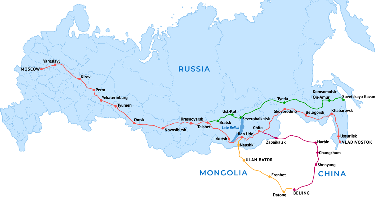
It appears to me that if one wants to make progress in mathematics, one should study the masters and not the pupils. - Niels Henrik Abel.
Nothing is better than reading and gaining more and more knowledge - Stephen William Hawking.
Offline
#2663 2025-12-15 20:58:17
- Jai Ganesh
- Administrator
- Registered: 2005-06-28
- Posts: 53,831
Re: Miscellany
2463) Flight Data Recorder
Gist
A flight data recorder (FDR), part of the "black box," is a rugged device that records crucial aircraft operational data (altitude, speed, heading, etc.) and audio (CVR) for accident investigation, designed to survive extreme impacts, heat, and water to help determine crash causes and improve aviation safety, with modern units capturing 25+ hours of info in bright orange, crash-survivable casings with locator beacons.
A flight data recorder (FDR; also ADR, for accident data recorder) is an electronic device employed to record instructions sent to any electronic systems on an aircraft. The data recorded by the FDR are used for accident and incident investigation.
Summary
A flight recorder is an electronic recording device placed in an aircraft for the purpose of facilitating the investigation of aviation accidents and incidents. The device may be referred to colloquially as a "black box", an outdated name which has become a misnomer because they are required to be painted bright orange, to aid in their recovery after accidents.
There are two types of flight recording devices: the flight data recorder (FDR) preserves the recent history of the flight by recording of dozens of parameters collected several times per second; the voice recorder (CVR) preserves the recent history of the sounds in the math, including the conversation of the pilots. The two devices may be combined into a single unit. Together, the FDR and CVR document the aircraft's flight history, which may assist in any later investigation.
The two flight recorders are required by the International Civil Aviation Organization to be capable of surviving conditions likely to be encountered in a severe aircraft accident. They are specified to withstand an impact of 3400 g and temperatures of over 1,000 °C (1,830 °F) by EUROCAE ED-112. They have been a mandatory requirement in commercial aircraft in the United States since 1967. After the unexplained disappearance of Malaysia Airlines Flight 370 in 2014, commentators have called for live streaming of data to the ground, as well as extending the battery life of the underwater locator beacons.
Details
Flight Data Recorder (FDR) - device used to record specific aircraft performance parameters. The purpose of an FDR is to collect and record data from a variety of aircraft sensors onto a medium designed to survive an accident.
An FDR has historically been one of two types of "flight recorder" carried on aircraft, the other being a math voice recorder (CVR). Where both types of recorder are fitted, they are now sometimes combined into a single unit (ICAO Definition: Combination recorders). Combination recorders need to meet the flight recorder equipage requirements as specifically detailed in ICAO Annex 6 - Operation of Aircraft.
These combination recorders are sometimes referred to as Digital Voice and Data Recorders (DVDR). Some models originally recorded 25 hours of flight data and two hours of audio. However, rules adopted by the International Civil Aviation Organisation (ICAO) and the European Union Aviation Safety Agency (EASA) require 25 hours of audio for commercial aircraft with a maximum takeoff weight of 27,000 kg (60,000 lbs) or more, manufactured after January 1, 2021.
Some regulators require a minimum of two DVDRs. For example, U.S. Federal Aviation Administration (FAA) regulations state: "Two separate recorders are required for airplanes. Therefore, a single combination CVR/DFDR may not serve as both the required DFDR and the required CVR." However, the FAA allows one combination unit on rotorcraft, as long as no single electrical failure can disable both the CVR and DFDR functions. The FAA also plans a 25-hour CVR requirement.
Other ICAO Requirements
According to the provisions in ICAO Annex 6 - Operation of Aircraft, Vol 1 and Vol. III, a Type I FDR shall shall record the parameters required to determine accurately the aeroplane flight path, speed, attitude, engine power, configuration and operation. Types II and IIA FDRs shall record the parameters required to determine accurately the aeroplane flight path, speed, attitude, engine power and configuration of lift and drag devices.
The detailed list of parameters to be recorded by FDRs is provided in section 6.3 “Flight recorders” and at Attachement D to Annex 6, Vol. I. Furthermore, provisions in section 6.3 specify the aircraft equipage requirements depending on the maximum certificated takeoff mass and the date of first issue of the individual certificate of airworthiness. For example, provision 6.3.6 of Annex 6, Vol. I states that, all aeroplanes of a maximum certificated takeoff mass of over 5,700 kg for which the individual certificate of airworthiness is first issued after 1 January 2005 shall be equipped with a Type IA FDR.
According to ICAO SARPS, combination recorders (FDR/CVR) can only be used to meet the flight recorder equipage requirements as specifically indicated in ICAO Annex 6 (Vol I and Vol III, Attachment D).
Annex 6 amendments that took effect in 2019 state that FDR and CVR data may be used only for safety-related purposes with appropriate safeguards, and for criminal proceedings.
Other FAA Requirements
U.S. Federal Aviation Administration (FAA) requirements regarding FDRs for transport category aircraft include the following provisions:
* The FDR receives electrical power from a bus that provides maximum reliability without jeopardising service to essential or emergency loads.
* The FDR remains powered for as long as possible without jeopardising emergency operation of the airplane.
* There is an aural or visual means for preflight checking of the recorder for proper recording of data in the storage medium.
* Any single electrical failure does not disable both the FDR and the CVR.
* Each recorder must be bright orange or bright yellow, must have reflective tape attached, and have an underwater locating device.
* The FDR is supplied with flight data that meets specified accuracy requirements.
Objective
The recorder is installed in the most crash survivable part of the aircraft, usually the tail section. The data collected in the FDR system can help investigators determine whether an accident was caused by pilot error, by an external event (such as windshear), or by an airplane system problem. Furthermore, these data have contributed to airplane system design improvements and the ability to predict potential difficulties as airplanes age. An example of the latter is using FDR data to monitor the condition of a high-hours engine. Evaluating the data could be useful in making a decision to replace the engine before a failure occurs.
Additional Information
A flight recorder is an instrument that records the performance and condition of an aircraft in flight. Governmental regulatory agencies require these devices on commercial aircraft to make possible the analysis of crashes or other unusual occurrences. Flight recorders actually consist of two functional devices, the flight data recorder (FDR) and the voice recorder (CVR), though sometimes these two devices are packaged together in one combined unit. The FDR records many variables, not only basic aircraft conditions such as airspeed, altitude, heading, vertical acceleration, and pitch but also hundreds of individual instrument readings and internal environmental conditions. The CVR records verbal communication between crew members within the aircraft’s math as well as voice transmissions by radio. Aircraft sounds audible in the math are also caught on the recorder. Flight recorders are commonly carried in the tail of the aircraft, which is usually the structure that is subject to the least impact in the event of a crash. In spite of the popular name black box, flight recorders are painted a highly visible vermilion colour known as “international orange.”
The voice and instrument data processed by the flight recorder are stored in digital format on solid-state memory boards. At least 2 hours of math sound and up to 25 hours of flight data are stored, new data continuously replacing the old. The memory boards are housed within a box or cylinder called the crash-survivable memory unit. This is the only truly survivable component of the flight recorder; the other components, such as the data processor, are not necessary for retrieval of data. Consisting of a heavy stainless steel shell wrapped within layers of insulating material and covered by an aluminum housing, a memory unit is expected to survive impacts of 3,400 g (units of gravitational acceleration), flame temperatures as high as 1,100 °C (2,000 °F), and pressures encountered at 6,000 metres (20,000 feet) underwater. In the event of a crash at sea, flight recorders are equipped with a sonar device that is designed to emit an ultrasonic locator signal for at least 30 days.
In 1939 French engineers François Hussenot and Paul Beaudouin invented a flight recorder, the “type HB” (later called the “hussenograph”), that recorded altitude and speed information on a piece of photographic film. During World War II, analyzing crashes of military aircraft became important. In the United Kingdom, engineers Len Harrison and Vic Husband developed a system that recorded aircraft data on copper foil and could survive a crash. In Finland, engineer Veijo Hietala in 1942 developed a unit nicknamed the “Mata-Hari” that recorded test-flight data on photosensitive paper, which sometimes survived a crash. The U.S. Army Air Forces experimented with recording math voice data on a magnetic wire.
As civil aviation developed in the years after World War II, “crash-survivable” flight recorders came to be seen as a valuable tool in analyzing aviation disasters and contributing to the design of safer aircraft. However, truly serviceable flight recorders that had any chance of surviving plane crashes were not produced until several years after the war. A series of disastrous crashes of De Havilland Comet jetliners in 1953–54 spurred David Warren, a scientist at Australia’s Aeronautical Research Laboratory (ARL), to design the first combined FDR and CVR. The recording medium for Warren’s ARL Flight Memory Unit was steel wire of the type then being used in magnetic audio recorders. Warren’s invention became the basis for subsequent flight recorders. Although Warren’s recorder, as produced commercially by S. Davall & Son beginning in 1960, was housed in an egg-shaped casing that was painted red, the term black box, which arose during World War II as slang for sensitive aircraft components that were encased in black metal boxes, was applied to the device.
Parallel developments occurred elsewhere in the world. In the United States, James J. Ryan, an engineer employed by General Mills, in 1953 developed the VGA Flight Recorder, which sensed changes in velocity (V), gravitational forces (G), and altitude (A) and inscribed the measurements on a slowly moving strip of aluminum foil. As released in 1953 and sold by General Mills to the Lockheed Aircraft Company, the entire apparatus was enclosed in a yellow-painted spherical shell. Numerous other devices were produced employing various recording media, from metal strips to, eventually, magnetic tape.
During the 1960s, crash-protected FDRs and CVRs became mandatory on airliners around the world. Most flight recorders employed magnetic tape, but during the 1990s a great advancement came with the advent of solid-state memory devices. Memory boards are more survivable than recording tape, and the data stored on them can be retrieved quickly by a computer carrying the proper software. A complete picture can be created of conditions on the aircraft during the recorded period, including a computer-animated diagram of the aircraft’s positions and movements. Verbal exchanges and math sounds retrieved from CVR data are transcribed into documents that are made available to investigators along with the actual recordings. The release of these materials to the public is strictly regulated.

It appears to me that if one wants to make progress in mathematics, one should study the masters and not the pupils. - Niels Henrik Abel.
Nothing is better than reading and gaining more and more knowledge - Stephen William Hawking.
Offline
#2664 2025-12-21 18:01:08
- Jai Ganesh
- Administrator
- Registered: 2005-06-28
- Posts: 53,831
Re: Miscellany
2464) Canada - The Country With The Longest Coastline In The World
Gist
While the common name is simply Canada, its historical full name, used at Confederation in 1867, was the Dominion of Canada, a term dropped from official use with the Canada Act in 1982, though it's still sometimes referenced. Today, "Canada" is the legal name, reflecting its status as a sovereign nation, constitutional monarchy, and parliamentary democracy.
Is Canada a good place to live?
Yes, Canada is widely considered a very good place to live due to its high quality of life, safety, strong social programs (like universal healthcare and education), multiculturalism, and abundant natural beauty, but it comes with challenges like high living costs in major cities, long winter seasons, and potential integration difficulties for newcomers.
Summary
Canada, is the second largest country in the world in area (after Russia), occupying roughly the northern two-fifths of the continent of North America.
Despite Canada’s great size, it is one of the world’s most sparsely populated countries. This fact, coupled with the grandeur of the landscape, has been central to the sense of Canadian national identity, as expressed by the Dublin-born writer Anna Brownell Jameson, who explored central Ontario in 1837 and remarked exultantly on “the seemingly interminable line of trees before you; the boundless wilderness around you; the mysterious depths amid the multitudinous foliage, where foot of man hath never penetrated…the solitude in which we proceeded mile after mile, no human being, no human dwelling within sight.” Although Canadians are comparatively few in number, they have crafted what many observers consider to be a model multicultural society, welcoming immigrant populations from every other continent. In addition, Canada harbours and exports a wealth of natural resources and intellectual capital equaled by few other countries.
Canada is officially bilingual in English and French, reflecting the country’s history as ground once contested by two of Europe’s great powers. The word Canada is derived from the Huron-Iroquois kanata, meaning a village or settlement. In the 16th century, French explorer Jacques Cartier used the name Canada to refer to the area around the settlement that is now Quebec city. Later, Canada was used as a synonym for New France, which, from 1534 to 1763, included all the French possessions along the St. Lawrence River and the Great Lakes. After the British conquest of New France, the name Quebec was sometimes used instead of Canada. The name Canada was fully restored after 1791, when Britain divided old Quebec into the provinces of Upper and Lower Canada (renamed in 1841 Canada West and Canada East, respectively, and collectively called Canada). In 1867 the British North America Act created a confederation from three colonies (Nova Scotia, New Brunswick, and Canada) called the Dominion of Canada. The act also divided the old colony of Canada into the separate provinces of Ontario and Quebec. Dominion status allowed Canada a large measure of self-rule, but matters pertaining to international diplomacy and military alliances were reserved to the British crown. Canada became entirely self-governing within the British Empire in 1931, though full legislative independence was not achieved until 1982, when Canada obtained the right to amend its own constitution.
Canada shares a 5,525-mile- (8,890-km-) long border with the United States (including Alaska)—the longest border in the world not patrolled by military forces—and the overwhelming majority of its population lives within 185 miles (300 km) of the international boundary. Although Canada shares many similarities with its southern neighbour—and, indeed, its popular culture and that of the United States are in many regards indistinguishable—the differences between the two countries, both temperamental and material, are profound. “The central fact of Canadian history,” observed the 20th-century literary critic Northrop Frye, is “the rejection of the American Revolution.” Contemporary Canadians are inclined to favour orderly central government and a sense of community over individualism; in international affairs, they are more likely to serve the role of peacemaker instead of warrior, and, whether at home or abroad, they are likely to have a pluralistic way of viewing the world. More than that, Canadians live in a society that in most legal and official matters resembles Britain—at least in the English-speaking portion of the country. Quebec, in particular, exhibits French adaptations: more than three-fourths of its population speaks French as their primary language. The French character in Quebec is also reflected in differences in religion, architecture, and schooling. Elsewhere in Canada, French influence is less apparent, confined largely to the dual use of French and English for place names, product labels, and road signs. The French and British influences are supplemented by the cultures of the country’s Native American peoples (in Canada often collectively called the First Nations) and Inuit peoples, the former being far greater in number and the latter enjoying semiautonomous status in Canada’s newest territory, Nunavut. In addition, the growing number of immigrants from other European countries, Southeast Asia, and Latin America has made Canada even more broadly multicultural.
Canada has been an influential member of the Commonwealth and has played a leading role in the organization of French-speaking countries known as La Francophonie. It was a founding member of the United Nations and has been active in a number of major UN agencies and other worldwide operations. In 1989 Canada joined the Organization of American States and signed a free trade agreement with the United States, a pact that was superseded in 1992 by the North American Free Trade Agreement (which also includes Mexico). A founding member (1961) of the Organisation for Economic Co-operation and Development, Canada is also a member of the Group of Seven (G7), which includes the world’s seven largest industrial democracies and, as the Group of Eight (G8), had included Russia until it was indefinitely suspended from membership in 2014.
The national capital is Ottawa, Canada’s fourth largest city. It lies some 250 miles (400 km) northeast of Toronto and 125 miles (200 km) west of Montreal, respectively Canada’s first and second cities in terms of population and economic, cultural, and educational importance. The third largest city is Vancouver, a centre for trade with the Pacific Rim countries and the principal western gateway to Canada’s developing interior. Other major metropolitan areas include Calgary and Edmonton, Alberta; Quebec city, Quebec; and Winnipeg, Manitoba.
Details
Canada is a country in North America. Its ten provinces and three territories extend from the Atlantic Ocean to the Pacific Ocean and northward into the Arctic Ocean, making it the second-largest country by total area, with the longest coastline of any country. Its border with the United States is the longest international land border. The country is characterized by a wide range of both meteorologic and geological regions. With a population of over 41 million, it has widely varying population densities, with the majority residing in its urban areas and large areas being sparsely populated. Canada's capital is Ottawa and its three largest metropolitan areas are Toronto, Montreal, and Vancouver.
Indigenous peoples have continuously inhabited what is now Canada for thousands of years. Beginning in the 16th century, British and French expeditions explored and later settled along the Atlantic coast. As a consequence of various armed conflicts, France ceded nearly all of its colonies in North America in 1763. In 1867, with the union of three British North American colonies through Confederation, Canada was formed as a federal dominion of four provinces. This began an accretion of provinces and territories resulting in the displacement of Indigenous populations, and a process of increasing autonomy from the United Kingdom. This increased sovereignty was highlighted by the Statute of Westminster, 1931, and culminated in the Canada Act 1982, which severed the vestiges of legal dependence on the Parliament of the United Kingdom.
Canada is a parliamentary democracy and a constitutional monarchy in the Westminster tradition. The country's head of government is the prime minister, who holds office by virtue of their ability to command the confidence of the elected House of Commons and is appointed by the governor general, representing the monarch of Canada, the ceremonial head of state. The country is a Commonwealth realm and is officially bilingual (English and French) in the federal jurisdiction. It is very highly ranked in international measurements of government transparency, quality of life, economic competitiveness, innovation, education and human rights. It is one of the world's most ethnically diverse and multicultural nations, the product of large-scale immigration. Canada's long and complex relationship with the United States has had a significant impact on its history, economy, and culture.
A developed country, Canada has a high nominal per capita income globally and its advanced economy ranks among the largest in the world by nominal GDP, relying chiefly upon its abundant natural resources and well-developed international trade networks. Recognized as a middle power, Canada's support for multilateralism and internationalism has been closely related to its foreign policies of peacekeeping and aid for developing countries. Canada promotes its domestically shared values through participation in multiple international organizations and forums.
Geography
By total area (including its waters), Canada is the second-largest country. By land area alone, Canada ranks fourth, due to having the world's largest area of fresh water lakes. Stretching from the Atlantic Ocean in the east, along the Arctic Ocean to the north, and to the Pacific Ocean in the west, the country encompasses 9,984,670 square kilometres (3,855,100 sq mi) of territory. Canada also has vast maritime terrain, with the world's longest coastline of 243,042 kilometres (151,019 mi). In addition to sharing the world's largest land border with the United States—spanning 8,891 kilometres (5,525 mi)—Canada shares a land border with Greenland (and hence the Kingdom of Denmark) to the northeast, on Hans Island, and a maritime boundary with France's overseas collectivity of Saint Pierre and Miquelon to the southeast. Canada is also home to the world's northernmost settlement, Canadian Forces Station Alert, on the northern tip of Ellesmere Island—latitude 82.5°N—which lies 817 kilometres (508 mi) from the North Pole. In latitude, Canada's most northerly point of land is Cape Columbia in Nunavut at 83°6′41″N, with its southern extreme at Middle Island in Lake Erie at 41°40′53″N. In longitude, Canada's land extends from Cape Spear, Newfoundland, at 52°37'W, to Mount St. Elias, Yukon Territory, at 141°W.
Canada can be divided into seven physiographic regions: the Canadian Shield, the Interior Plains, the Great Lakes–St. Lawrence Lowlands, the Appalachian region, the Western Cordillera, Hudson Bay Lowlands, and the Arctic Archipelago. Boreal forests prevail throughout the country, ice is prominent in northern Arctic regions and through the Rocky Mountains, and the relatively flat Canadian Prairies in the southwest facilitate productive agriculture. The Great Lakes feed the St. Lawrence River (in the southeast) where the lowlands host much of Canada's economic output. Canada has over 2,000,000 lakes—563 of which are larger than 100 square kilometres (39 sq mi)—containing much of the world's fresh water. There are also fresh-water glaciers in the Canadian Rockies, the Coast Mountains, and the Arctic Cordillera. Canada is geologically active, having many earthquakes and potentially active volcanoes.
Climate
Average winter and summer high temperatures across Canada vary from region to region. Winters can be harsh in many parts of the country, particularly in the interior and Prairie provinces, which experience a continental climate, where daily average temperatures are near −15 °C (5 °F), but can drop below −40 °C (−40 °F) with severe wind chills. In non-coastal regions, snow can cover the ground for almost six months of the year, while in parts of the north snow can persist year-round. Coastal British Columbia has a temperate climate, with a mild and rainy winter. On the east and west coasts, average high temperatures are generally in the low 20s °C (70s °F), while between the coasts, the average summer high temperature ranges from 25 to 30 °C (77 to 86 °F), with temperatures in some interior locations occasionally exceeding 40 °C (104 °F).
Much of Northern Canada is covered by ice and permafrost. The future of the permafrost is uncertain because the Arctic has been warming at three times the global average as a result of climate change in Canada. Canada's annual average temperature over land has risen by 1.7 °C (3.1 °F), with changes ranging from 1.1 to 2.3 °C (2.0 to 4.1 °F) in various regions, since 1948. The rate of warming has been higher across the North and in the Prairies. In the southern regions of Canada, air pollution from both Canada and the United States—caused by metal smelting, burning coal to power utilities, and vehicle emissions—has resulted in acid rain, which has severely impacted waterways, forest growth, and agricultural productivity. Canada is one of the largest greenhouse gas emitters globally, with emissions increased by 16.5 percent between 1990 and 2022.
Additional Information
Canada is a vast and rugged land. From north to south it spans more than half the Northern Hemisphere. From east to west it stretches almost 4,700 miles (7,560 kilometers) across six time zones. It is the second largest country in the world, but it has only one-half of one percent of the world's population.
Canada features black-blue lakes, numerous rivers, majestic western mountains, rolling central plains, and forested eastern valleys. The Canadian Shield, a hilly region of lakes and swamps, stretches across northern Canada and has some of the oldest rocks on Earth.
Canada's far north lies in the frozen grip of the Arctic, where ice, snow, and glaciers dominate the landscape. Few trees grow here, and farming is not practical. Native Canadians, called First Nations people, live in this region by hunting and fishing.
Canada's remote north and extensive forests are home to wildlife, from bears, wolves, beavers, deer, mountain lions, and bighorn sheep to smaller animals like raccoons, otters, and rabbits. The country's lakes and rivers, which contain about 20 percent of all fresh water on Earth, are full of fish such as trout and salmon.
Canada's prairies in the south are home to bison and pronghorn antelope. Farther north are Canada's sprawling evergreen forests, which have lots of wildlife, including moose and black bears. Even farther north is the cold, bare tundra, where herds of caribou and musk ox live.
Canadians work hard to protect the native wildlife. Canada has 41 national parks and three marine conservation areas. Nevertheless, species like wolves, lynx, and Atlantic fish have been overhunted and overfished.

It appears to me that if one wants to make progress in mathematics, one should study the masters and not the pupils. - Niels Henrik Abel.
Nothing is better than reading and gaining more and more knowledge - Stephen William Hawking.
Offline
#2665 2025-12-26 21:52:08
- Jai Ganesh
- Administrator
- Registered: 2005-06-28
- Posts: 53,831
Re: Miscellany
2465) Brainstem
Gist
The brainstem is the structure that connects the cerebrum of the brain to the spinal cord and cerebellum. It is composed of three sections in descending order: the midbrain, pons, and medulla oblongata.
The brainstem is the vital stalk-like structure connecting the cerebrum and cerebellum to the spinal cord, controlling essential life functions like breathing, heart rate, blood pressure, and consciousness, while also relaying sensory/motor signals and housing nuclei for most cranial nerves (III-XII). It's made of three parts—the midbrain, pons, and medulla oblongata—and is crucial for sleep, balance, swallowing, vision, hearing, and facial movement.
Summary
The brainstem (or brain stem) is the posterior stalk-like part of the brain that connects the cerebrum with the spinal cord. In the human brain, the brainstem is composed of the midbrain, the pons, and the medulla oblongata. The midbrain is continuous with the thalamus of the diencephalon through the tentorial notch, and sometimes the diencephalon is included in the brainstem.
The brainstem is very small, making up around only 2.6 percent of the brain's total weight. It has the critical roles of regulating heart and respiratory function, helping to control heart rate and breathing rate. It also provides the main motor and sensory nerve supply to the face and neck via the cranial nerves. Ten pairs of cranial nerves come from the brainstem. Other roles include the regulation of the central nervous system and the body's sleep cycle. It is also of prime importance in the conveyance of motor and sensory pathways from the rest of the brain to the body, and from the body back to the brain. These pathways include the corticospinal tract (motor function), the dorsal column-medial lemniscus pathway (fine touch, vibration sensation, and proprioception), and the spinothalamic tract (pain, temperature, itch, and crude touch).
Clinical significance
Diseases of the brainstem can result in abnormalities in the function of cranial nerves that may lead to visual disturbances, pupil abnormalities, changes in sensation, muscle weakness, hearing problems, vertigo, swallowing and speech difficulty, voice change, and co-ordination problems. Localizing neurological lesions in the brainstem may be very precise, although it relies on a clear understanding on the functions of brainstem anatomical structures and how to test them.
Brainstem stroke syndrome can cause a range of impairments including locked-in syndrome.
Duret haemorrhages are areas of bleeding in the midbrain and upper pons due to a downward traumatic displacement of the brainstem.
Cysts known as syrinxes can affect the brainstem, in a condition, called syringobulbia. These fluid-filled cavities can be congenital, acquired or the result of a tumor.
Criteria for claiming brainstem death in the UK have developed in order to make the decision of when to stop ventilation of somebody who could not otherwise sustain life. These determining factors are that the patient is irreversibly unconscious and incapable of breathing unaided. All other possible causes must be ruled out that might otherwise indicate a temporary condition. The state of irreversible brain damage has to be unequivocal. There are brainstem reflexes that are checked for by two senior doctors so that imaging technology is unnecessary. The absence of the cough and gag reflexes, of the corneal reflex and the vestibulo-ocular reflex need to be established; the pupils of the eyes must be fixed and dilated; there must be an absence of motor response to stimulation and an absence of breathing marked by concentrations of carbon dioxide in the arterial blood. All of these tests must be repeated after a certain time before death can be declared.
Details
Your brainstem connects your brain to your spinal cord. It sits at the bottom of your brain and includes the midbrain, pons and medulla oblongata. Your brainstem sends messages to the rest of your body to regulate balance, breathing, heart rate and more.
What is the brainstem?
Your brainstem connects your brain to your spinal cord. It sits near the bottom of your brain. It helps regulate vital body functions that you don’t have to think about, like breathing and your heart rate. Your brainstem also helps with your balance, coordination and reflexes.
It’s part of your central nervous system and has three parts that work together. Each part does a specific job to help you adapt to your environment, move and function.
Function:
What is the function of the brainstem?
Your brainstem sends messages back and forth between your brain and other parts of your body. It regulates many involuntary actions — functions your body performs automatically, like:
* Balance.
* Blood pressure.
* Breathing.
* Eye movements.
* Facial movements and sensations.
* Hearing.
* Heart rate.
* Sleep and wakefulness.
* Swallowing.
* Taste.
What are brainstem reflexes?
Brainstem reflexes are your body’s immediate and involuntary motor responses that help you survive and adapt to changes in your environment. You aren’t consciously thinking about performing these actions. Instead, your brainstem automatically tells your body to do them.
Brainstem reflexes include:
* Cardiovascular reflexes: A group of reflexes that regulate your heartbeat and blood pressure.
* Gag reflex: This reflex protects your airways.
* Swallowing reflex: This reflex moves food and liquids from your mouth to your stomach.
* Pupillary light reflex: This adjusts the size of your pupil (the black center of your eye) to adapt to lighting changes.
* Vestibulo-ocular reflex: This reflex steadies your eyes when you move your head or the rest of your body.
* Respiratory reflexes: A group of reflexes that regulate breathing, coughing and sneezing.
Anatomy:
Where is the brainstem located?
Your brainstem is located near the bottom of your brain, at the back of your skull. It connects your brain to your spinal cord.
What are the three parts of the brainstem?
Your brainstem is made up of three parts:
* Midbrain: The top part of your brainstem. The midbrain is involved in several functions, including motor control, particularly eye movements and processing of vision and hearing.
* Pons: The middle portion of your brainstem that coordinates face and eye movements, facial sensations, hearing and balance.
* Medulla oblongata: The bottom part of your brainstem that regulates your breathing, heartbeat, blood pressure and swallowing.
Your brainstem also contains your reticular activating system (RAS). The RAS is a network of neurons (nerve cells that carry electrical signals and chemicals through your brain). It works with your thalamus to manage your:
* Wakefulness (alertness).
* Awareness of your surroundings.
* Sleep and wake cycles.
Brainstem cranial nerves
Your brainstem contains 10 of the 12 cranial nerves (nerves that start in your brain) including cranial nerves 3 through 12. They help with your movements, sensations, taste and hearing.
What does the brainstem look like?
Your brainstem looks like a flower stalk or a stem of a plant. It’s a tube-like structure made of neural (or nervous system) tissue. It’s about 2 to 3 inches (5 to 7 centimeters) long.
Additional Information
Brainstem is area at the base of the brain that lies between the deep structures of the cerebral hemispheres and the cervical spinal cord and that serves a critical role in regulating certain involuntary actions of the body, including heartbeat and breathing. The brainstem is divided into three sections in humans: the midbrain (mesencephalon), the pons (metencephalon), and the medulla oblongata (myelencephalon).
The brainstem houses many of the control centres for vital body functions, such as swallowing, breathing, and vasomotor control. All of the cranial nerve nuclei, except those associated with olfaction and vision, are located in the brainstem, providing motor and sensory function to structures of the cranium, including the facial muscles, tongue, pharynx, and larynx, as well as supplying the senses of taste, equilibrium, and hearing. The brainstem also has nuclei important for sympathetic and parasympathetic autonomic functions. All efferent and afferent pathways between the cerebrum and cerebellum course through the brainstem, and many of them decussate, or cross, within this structure.
Because of the important neural structures concentrated in this small portion of the nervous system, even very small lesions of the brainstem may have profound effects. Speech disorders, vestibular disturbance, abnormal consciousness, dysphagia, and respiratory disturbance are a few examples of possible outcomes of brainstem disorders. Such disorders can be caused by trauma, tumours, strokes, infections, and demyelination (multiple sclerosis). Complete loss of brainstem function is regarded by some experts as equivalent to brain death.

It appears to me that if one wants to make progress in mathematics, one should study the masters and not the pupils. - Niels Henrik Abel.
Nothing is better than reading and gaining more and more knowledge - Stephen William Hawking.
Offline
#2666 2025-12-27 21:58:41
- Jai Ganesh
- Administrator
- Registered: 2005-06-28
- Posts: 53,831
Re: Miscellany
2466) Blood falls
Gist
Blood Falls is truly one of the most exciting spots to visit in Antarctica, which is best visited by boat. It gets its name because it's a waterfall that happens to be a shockingly-bright red color, similar to blood. However, the red color is thought to come from iron.
Blood Falls is a unique landform, as it did not originate from glacial melted water typically found in other continental glaciers. Instead a cascade of iron rich hypersaline water, originally trapped underground for millions of years, escaped to the Earth's surface via fissures under Taylor Glacier in East Antarctica.
Summary:
Where is Blood Falls located?
• Blood Falls, is located in Taylor Valley.
• Taylor Valley is one of the McMurdo Dry Valleys (MDV) in the Transantarctic Mountains. It is located between Asgard Range in the north and Kukri Hills in the south, containing numerous glaciers, lakes and rivers.
• Approximately 29 kilometres long, Taylor Valley extends from the retreating Taylor Glacier in the west to McMurdo Sound in the east.
• Subglacial water flows to Earth’s surface from the terminus of Taylor Glacier onto ice covered Lake Bonney in Taylor Valley.
What is the environment surrounding Blood Falls?:
Climate
Taylor Valley, one of the McMurdo Dry Valleys (MDV), encounters a freezing desert environment. Located in a rain shadow area behind mountains, the valleys experience low precipitation, mean annual temperature -19.8°C, and strong katabatic winds that reach 320 kilometres per hour. The winds evaporate all moisture, hence hindering the formation of ice and snow that covers most of Antarctica.
Taylor Valley and the other MDV encompass the largest ice-free region in Antarctica, with a combined area of Sq km 4500. The average moisture is less than 6mmpa, generally falling in the form of snow and summer glacial melt.
How was Blood Falls formed?
During a geological period called the Pliocene Epoch, about five million years ago, global warming caused East Antarctica’s ice sheets to melt and sea levels to rise about 20 metres. Taylor Valley was flooded and developed into a deep fiord.
• Around 5 million years ago sea levels rose, flooding East Antarctica. This created a salty inland lake
• Around 3 million years later, glaciers formed over the saline lake
• Around 2 million years ago a sub-glacial lake of saltwater became trapped and isolated. The frozen glacier surrounding the lake acted as a ‘time capsule’, preserving microbial species.
Research from University of Alaska, calculates that salt water took approximately 1.5 million years to finally reach Blood Falls as it made its way through fissures and channels in the glacier.
What caused the red colour in Blood Falls?
• Earliest explorers noticed the stain at the terminus of the glacier and speculated that red algae was responsible for the bright colour. Investigations later found the water was unsuitable for the growth and survival of algae.
• In 2009, scientists discovered the red colour was due to high levels of iron oxide in saltwater from a network of subglacial rivers and a subglacial lake.
Details
Blood Falls is an outflow of an iron(III) oxide–tainted plume of saltwater, flowing from the tongue of Taylor Glacier onto the ice-covered surface of West Lake Bonney in the Taylor Valley of the McMurdo Dry Valleys in Victoria Land, East Antarctica.
Iron-rich hypersaline water sporadically emerges from small fissures in the ice cascades. The saltwater source is a subglacial pool of unknown size overlain by about 400 metres (1,300 ft) of ice, several kilometers from its tiny outlet at Blood Falls.
The reddish deposit was found in 1911 by the Australian geologist Thomas Griffith Taylor, who first explored the valley that bears his name. The Antarctica pioneers first attributed the red color to red algae, but later it was proven to be due to iron oxides.
Geochemistry
Poorly soluble hydrous ferric oxides are deposited at the surface of ice after the ferrous ions present in the unfrozen saltwater are oxidized in contact with atmospheric oxygen. The more soluble ferrous ions initially are dissolved in old seawater trapped in an ancient pocket remaining from the Antarctic Ocean when a fjord was isolated by the glacier in its progression during the Miocene period, some 5 million years ago, when the sea level was higher than today.
Unlike most Antarctic glaciers, the Taylor Glacier is not frozen to the bedrock, probably because of the presence of salts concentrated by the crystallization of the ancient seawater imprisoned below it. Salt cryo-concentration occurred in the deep relict seawater when pure ice crystallized and expelled its dissolved salts as it cooled down because of the heat exchange of the captive liquid seawater with the enormous ice mass of the glacier. As a consequence, the trapped seawater was concentrated in brines with a salinity two to three times that of the mean ocean water. A second mechanism sometimes also explaining the formation of hypersaline brines is the water evaporation of surface lakes directly exposed to the very dry polar atmosphere in the McMurdo Dry Valleys. The analyses of stable isotopes of water allow, in principle, to distinguish between both processes as long as there is no mixing between differently formed brines.
Hypersaline fluid, sampled fortuitously through a crack in the ice, was oxygen-free and rich in sulfate and ferrous ion. Sulfate is a remnant geochemical signature of marine conditions, while soluble divalent iron was likely liberated under reducing conditions from the subglacial bedrock minerals weathered by microbial activity.
Microbial ecosystem
Chemical and microbial analyses both indicate that a rare subglacial ecosystem of autotrophic bacteria developed that metabolizes sulfate and ferric ions. According to geomicrobiologist Jill Mikucki at the University of Tennessee, water samples from Blood Falls contained at least 17 different types of microbes, and almost no oxygen. An explanation may be that the microbes use sulfate to respire with ferric ions and metabolize the trace levels of organic matter trapped with them. Such a metabolic process had never before been observed in nature.
A puzzling observation is the coexistence of ferrous and sulfate ions under anoxic conditions. No sulfide anions are found in the system. This suggests an intricate and poorly understood interaction between the sulfur and the iron biochemical cycles.
In December 2014, scientists and engineers led by Mikucki returned to Taylor Glacier and used a probe called IceMole, designed by a German collaboration, to melt into the glacier and directly sample the salty water (brine) that feeds Blood Falls.
Samples were analyzed, and revealed a cold (−7 °C (19 °F)), iron-rich (3.4 mM) subglacial brine (8% sodium chloride). From these samples, scientists isolated and characterized a type of bacteria capable of growing in salty water (halophilic), that thrives in the cold (psychrophile), and is heterotrophic, which they assigned to the genus Marinobacter. DNA bioinformatic analysis indicated the presence of at least four gene clusters involved in secondary metabolism. Two gene clusters are related to the production of aryl polyenes, which function as antioxidants that protect the bacteria from reactive oxygen species. Another gene cluster seems to be involved in terpene biosynthesis, most likely to produce pigments. Other bacteria identified are Thiomicrospira sp., and Desulfocapsa sp.
Implications for the Snowball Earth hypothesis
According to Mikucki et al. (2009), the now-inaccessible subglacial pool was sealed off 1.5 to 2 million years ago and transformed into a kind of "time capsule", isolating the ancient microbial population for a sufficiently long time to evolve independently of other similar marine organisms. It explains how other microorganisms could have survived when the Earth (according to the Snowball Earth hypothesis) was entirely frozen over.
Ice-covered oceans might have been the only refugium for microbial ecosystems when the Earth apparently was covered by glaciers at tropical latitudes during the Proterozoic eon about 650 to 750 million years ago.
Implications for astrobiology
This unusual place offers scientists a unique opportunity to study deep subsurface microbial life in extreme conditions without the need to drill deep boreholes in the polar ice cap, with the associated contamination risk of a fragile and still-intact environment.
The study of harsh environments on Earth is useful to understand the range of conditions to which life can adapt and to advance assessment of the possibility of life elsewhere in the Solar System, in places such as Mars or Europa, an ice-covered moon of Jupiter. Scientists of the NASA Astrobiology Institute speculate that these worlds could contain subglacial liquid water environments favorable to hosting elementary forms of life, which would be better protected at depth from ultraviolet and cosmic radiation than on the surface.
Additional Information
Amid Antarctica’s vast stretches of glittering white snow and ethereal blue glacier ice is the famous Blood Falls. It’s situated at the terminus of Taylor Glacier in the McMurdo Dry Valleys. Blood Falls is an iron-rich, hypersaline discharge phenomenon. And it spews bold streaks of bright-red brine from within the glacier onto the ice-covered surface of Lake Bonney.
Australian geologist Griffith Taylor was the first explorer to happen upon Blood Falls in 1911. It was during one of the earliest Antarctic expeditions. At the time, Taylor (incorrectly) attributed the color to the presence of red algae. The cause of this color was a mystery for nearly a century. But now we know that the iron-rich liquid turns red when it breaches the surface and oxidizes. In fact, this is the same process that gives iron a reddish hue when it rusts.
Blood Falls, named for its ruddy color, is not in fact a gush of blood from some unseen wound.
The color was initially chalked up to red algae, but a study in the Journal of Glaciology has uncovered its true origin using radar to scan the layers of ice from which the river pours.
The discovery came at the hands of a team of scientists, including National Geographic emerging explorer Erin C Pettit.
Located in Antarctica’s McMurdo Dry Valleys, the falls pour forth from Taylor Glacier, and the liquid bubbles up from fissures in the glacier’s surface. The flow was previously a mystery, as the mean temperature is 1.4 degrees Fahrenheit (-17 degrees Celsius) and little glacial melting can be seen at the surface.
Imaging from underneath the glacier helped solve the mystery, revealing a complex network of subglacial rivers and a subglacial lake—all filled with brine high in iron, giving the falls its reddish tint.
According to the study, the makeup of the brine explains the fact that it flows instead of freezes.
“The brine remains liquid within the subglacial and englacial environments through latent heat of freezing coupled with elevated salt content,” the study explains.
Iron-Filled, Salty Water
The lake under the glacier has an unusually salty consistency, and because saltwater has a lower freezing point than pure water and releases heat as it freezes, it melts the ice, enabling the rivers to flow.
This means that the glacier can support flowing water and also that this is the coldest glacier on Earth with constantly flowing water—though this water is so filled with iron that it looks like something else entirely.
The study also measured the amount of iron-rich brine in the river water and found the brine content increased as the measurements drew closer to the falls.
Water temperature and brine content were also found to be related: Cracks of various sizes in the glacier let brine into the glacier. Then the brine (pictured here in red to represent the amount of iron present in the water) begins to freeze, and the latent heat warms the ice around it, upping the brine concentration in the center of the cracks.

It appears to me that if one wants to make progress in mathematics, one should study the masters and not the pupils. - Niels Henrik Abel.
Nothing is better than reading and gaining more and more knowledge - Stephen William Hawking.
Offline
#2667 2025-12-31 17:29:40
- Jai Ganesh
- Administrator
- Registered: 2005-06-28
- Posts: 53,831
Re: Miscellany
2467) Eiffel Tower
Gist
The Eiffel Tower is famous for being an engineering marvel, the former tallest structure in the world, and a powerful, romantic symbol of Paris and France, initially built for the 1889 World's Fair but becoming a beloved icon through its unique design, stunning lights, and representation of French ingenuity and culture.
The most famous tourist attraction in France (and one of the best known in the world), the Eiffel Tower is 135 years old and is still considered a symbol of modernity and avant-garde in Paris.
Summary
On March 31, 1889, the Eiffel Tower is dedicated in Paris in a ceremony presided over by Gustave Eiffel, the tower’s designer, and attended by French Prime Minister Pierre Tirard, a handful of other dignitaries and 200 construction workers.
In 1889, to honor of the centenary of the French Revolution, the French government planned an international exposition and announced a design competition for a monument to be built on the Champ-de-Mars in central Paris. Out of more than 100 designs submitted, the Centennial Committee chose Eiffel’s plan of an open-lattice wrought-iron tower that would reach almost 1,000 feet above Paris and be the world’s tallest man-made structure. Eiffel, a noted bridge builder, was a master of metal construction and designed the framework of the Statue of Liberty that had recently been erected in New York Harbor.
Eiffel’s tower was greeted with skepticism from critics who argued that it would be structurally unsound, and indignation from others who thought it would be an eyesore in the heart of Paris. Unperturbed, Eiffel completed his great tower under budget in just two years. Only one worker lost his life during construction, which at the time was a remarkably low casualty number for a project of that magnitude. The light, airy structure was by all accounts a technological wonder and within a few decades came to be regarded as an architectural masterpiece.
The Eiffel Tower is 984 feet tall and consists of an iron framework supported on four masonry piers, from which rise four columns that unite to form a single vertical tower. Platforms, each with an observation deck, are at three levels. Elevators ascend the piers on a curve, and Eiffel contracted the Otis Elevator Company of the United States to design the tower’s famous glass-cage elevators.
The elevators were not completed by March 31, 1889, however, so Gustave Eiffel ascended the tower’s stairs with a few hardy companions and raised an enormous French tricolor on the structure’s flagpole. Fireworks were then set off from the second platform. Eiffel and his party descended, and the architect addressed the guests and about 200 workers. In early May, the Paris International Exposition opened, and the tower served as the entrance gateway to the giant fair.
The Eiffel Tower remained the world’s tallest man-made structure until the completion of the Chrysler Building in New York in 1930. Incredibly, the Eiffel Tower was almost demolished when the International Exposition’s 20-year lease on the land expired in 1909, but its value as an antenna for radio transmission saved it. It remains largely unchanged today and is one of the world’s premier tourist attractions.
Details
The Eiffel Tower is a wrought-iron lattice tower on the Champ de Mars in Paris, France. It is named after the engineer Gustave Eiffel, whose company designed and built the tower from 1887 to 1889.
Locally nicknamed "La dame de fer" (French for "Iron Lady"), it was constructed as the centrepiece of the 1889 World's Fair, and to crown the centennial anniversary of the French Revolution. Although initially criticised by some of France's leading artists and intellectuals for its design, it has since become a global cultural icon of France and one of the most recognisable structures in the world. The tower received 5,889,000 visitors in 2022. The Eiffel Tower is the most visited monument with an entrance fee in the world: 6.91 million people ascended it in 2015. It was designated a monument historique in 1964, and was named part of a UNESCO World Heritage Site ("Paris, Banks of the Seine") in 1991.
The tower is 330 metres (1,083 ft) tall, about the same height as an 81-storey building, and the tallest structure in Paris. Its base is square, measuring 125 metres (410 ft) on each side. During its construction, the Eiffel Tower surpassed the Washington Monument to become by far the tallest human-made structure in the world, a title it held for 41 years until the Chrysler Building in New York City was finished in 1930. It was the first structure in the world to surpass both the 200-metre and 300-metre mark in height. Due to the addition of a broadcasting aerial at the top of the tower in 1957, it is now taller than the Chrysler Building by 5.2 metres (17 ft). Excluding transmitters, the Eiffel Tower is the second tallest free-standing structure in France after the Millau Viaduct.
The tower has three levels for visitors, with restaurants on the first and second levels. The top level's upper platform is 276 m (906 ft) above the ground—the highest public observation deck in the European Union. Tickets can be purchased to ascend by stairs or lift to the first and second levels. The climb from ground level to the first level is over 300 steps, as is the climb from the first level to the second, making the entire ascent a 600-step climb. Although there is a staircase to the top level, it is usually accessible only by lift. On this top, third level, is a private apartment built for Gustave Eiffel, who decorated it with furniture made by Jean Lachaise and invited friends such as Thomas Edison.
Additional Information
Eiffel Tower, wrought-iron structure in Paris that is among the most famous landmarks in the world. It is also a technological masterpiece in building-construction history. It was designed and built (1887–89) by Gustave Eiffel and named in his honor.
Background and construction
When the French government was organizing the International Exposition of 1889 to celebrate the centenary of the French Revolution, a competition was held for designs for a suitable monument. More than 100 plans were submitted, and the Centennial Committee accepted that of the noted bridge engineer Gustave Eiffel. Eiffel’s concept of a 300-meter (984-foot) tower built almost entirely of open-lattice wrought iron aroused amazement, skepticism, and no little opposition on aesthetic grounds. When completed, the tower served as the entrance gateway to the exposition.
Nothing remotely like the Eiffel Tower had ever been built; it was twice as high as the dome of St. Peter’s in Rome or the Great Pyramid of Giza. In contrast to such older monuments, the tower was erected in only about two years (1887–89), with a small labor force, at slight cost. Making use of his advanced knowledge of the behavior of metal arch and metal truss forms under loading, Eiffel designed a light, airy, but strong structure that presaged a revolution in civil engineering and architectural design. And, after it opened to the public on May 15, 1889, it ultimately vindicated itself aesthetically.
Description and dimensions
The Eiffel Tower stands on four lattice-girder piers that taper inward and join to form a single large vertical tower. As they curve inward, the piers are connected to each other by networks of girders at two levels that afford viewing platforms for tourists. By contrast, the four semicircular arches at the tower’s base are purely aesthetic elements that serve no structural function. Because of their unique shape, which was dictated partly by engineering considerations but also partly by Eiffel’s artistic sense, the piers required elevators to ascend on a curve; the glass-cage machines designed by the Otis Elevator Company of the United States became one of the principal features of the building.
After the 1889 fair closed, Eiffel realized that the only way to save his monument would be to find new and profitable uses for it. He supervised changes to accommodate a meteorological station in 1890, a military telegraph station in 1903, and a laboratory for studying aerodynamics in 1909. Further modifications were made for the expositions of 1900, 1925, and 1937. Additions made for television transmission added about 20 meters (66 feet) to the height.
The tower stands 300 meters (984 feet) high. It rests on a base that is 5 meters (17 feet) tall, and the TV antenna atop the tower gives it a total elevation of 330 meters (1,083 feet). The Eiffel Tower was the tallest structure in the world until the topping off of the Chrysler Building in New York City in 1929.
Tourist attraction
The Eiffel Tower is arguably the most popular paid attraction in world. Some seven million people visit it each year. The tower features a museum, several restaurants, and the Gustave Eiffel Reception Room, which provides space for business conferences, expositions, cultural events, and social gatherings. In addition, several eateries and various shops are housed in the tower. An observation deck is located just under the antenna, at a height of 276 meters (906 feet).

It appears to me that if one wants to make progress in mathematics, one should study the masters and not the pupils. - Niels Henrik Abel.
Nothing is better than reading and gaining more and more knowledge - Stephen William Hawking.
Offline
#2668 2026-01-02 15:16:30
- Jai Ganesh
- Administrator
- Registered: 2005-06-28
- Posts: 53,831
Re: Miscellany
2468) Ant
Gist
Ants are incredibly strong, social insects with diverse roles in colonies, using chemical signals for communication, farming aphids and fungi, having two stomachs for food sharing, and "hearing" through ground vibrations rather than ears, existing as ancient creatures found almost everywhere except Antarctica, with some species forming massive global supercolonies.
An ant, from the family Formicidae, is a highly social insect living in organized colonies, known for cooperative behavior, clear labor division, and significant ecological roles, with over 10,000 species found globally, thriving in diverse habitats and exhibiting complex behaviors like farming aphids or hunting prey. These insects, related to wasps and bees (order Hymenoptera), have three body parts (head, thorax, abdomen) with elbowed antennae and powerful jaws, evolving from wasp ancestors, with a life cycle of egg, larva, pupa, and adult, often producing winged males/queens for mating.
Summary
Ants are eusocial insects of the family Formicidae and, along with the related wasps and bees, belong to the order Hymenoptera. Ants evolved from vespoid wasp ancestors in the Cretaceous period. More than 13,800 of an estimated total of 22,000 species have been classified. They are easily identified by their geniculate (elbowed) antennae and the distinctive node-like structure that forms their slender waists.
Ants form colonies that range in size from a few dozen individuals often living in small natural cavities to highly organised colonies that may occupy large territories with a sizeable nest (or nests) that consist of millions of individuals, in some cases they reach hundreds of millions of individuals in super colonies. Typical colonies consist of various castes of sterile, wingless females, most of which are workers (ergates), as well as soldiers (dinergates) and other specialised groups. Nearly all ant colonies also have some fertile males called "drones" and one or more fertile females called "queens" (gynes). The colonies are described as superorganisms because the ants appear to operate as a unified entity, collectively working together to support the colony.
Ants have colonised almost every landmass on Earth. The only places lacking indigenous ants are Antarctica and a few remote or inhospitable islands. Ants thrive in moist tropical ecosystems and may exceed the combined biomass of wild birds and mammals. Their success in so many environments has been attributed to their social organisation and their ability to modify habitats, tap resources, and defend themselves. Their long co-evolution with other species has led to mimetic, commensal, parasitic, and mutualistic relationships.
Ant societies have division of labour, communication between individuals, and an ability to solve complex problems. These parallels with human societies have long been an inspiration and subject of study. Many human cultures make use of ants in cuisine, medication, and rites. Some species are valued in their role as biological pest control agents. Their ability to exploit resources may bring ants into conflict with humans, however, as they can damage crops and invade buildings. Some species, such as the red imported fire ant (Solenopsis invicta) of South America, are regarded as invasive species in other parts of the world, establishing themselves in areas where they have been introduced accidentally.
Details
An ant, (family Formicidae), is any of approximately 10,000 species of insects that are social in habit and live together in organized colonies. Ants occur worldwide but are most numerous, both in numbers and in species, in tropical and subtropical regions. Ants are essential members of the ecosystems they inhabit, and some even serve as keystone species that have a disproportionately large effect on their ecological communities. Some ants are considered pests to humans, and a number are invasive species in areas outside their native ranges.
Physical description
Ants range in size from about 2 to 25 mm (about 0.08 to 1 inch). Their color is usually yellow, brown, red, or black. A few genera (e.g., Pheidole of North America) have a metallic luster.
Typically, an ant has a large head and a slender, oval abdomen joined to the thorax, or midsection, by a small waist. In all ants there are either one or two finlike extensions running across the thin waist region. The antennae are always elbowed. There are two sets of jaws: the outer pair is used for carrying objects such as food and for digging, and the inner pair is used for chewing. Some species, such as the debilitating bullet ant (Paraponera clavata), have a powerful sting at the tip of the abdomen.
Natural history
Ants are social insects, and the colony is a family community of which every ant is an integral unit. Apart from the community, any one individual cannot properly function or survive, and the larvae are completely dependent upon the continuous care of the adults. There are generally three castes, or classes, within a colony: queens, males, and workers. Male ants play no part in everyday nest activities. They live only for a short time, occur in limited numbers, and are virtual parasites of the colony, which must feed them. The fertile female, the queen, performs only one task: egg laying. The life cycle of the ant has four stages—egg, larva, pupa, and adult—and typically spans a period of 8 to 10 weeks for worker ants.
At certain times of the year, the winged males and virgin queens fly into the air, where the queen mates with a single male. During the flight he transfers to her seminal receptacle all the sperm she will require for the rest of her life, which may be as long as 15 years. The males die soon afterward, and the fertilized queen establishes a new nest or takes over the current nest. Her wings then drop off, and the bulky wing muscles degenerate, providing nutritive materials from the breakdown of the muscle tissue. As soon as the wings have fallen, her ovaries become functional, and egg laying begins. In primitive species, the queen leaves the nest and forages for food for the larvae. In more advanced forms, the queen rarely leaves the nest. She feeds so-called nutrition eggs or other food stores within her own body to the first brood. The larvae that survive in the nest develop into dwarf workers, which forage outside the nest for food to nourish additional larvae.
The essential work in the ant society—such as building the nest, feeding and tending the brood, and defending the nest—is performed by the workers, all of whom are female. The workers can be differentiated morphologically and physiologically as soldiers, outside workers, inside workers, and nest builders. In the division of labor among some ant forms, highly specialized types of polymorphism have developed. The Cryptocercus ants, for example, make nests in hollow stems of plants, then bore a circular entrance that remains under constant surveillance by special guards whose heads are modified into pluglike structures that fit the entrance. Each guard is relieved after several hours, and another guard takes its place; entrance guards are useless for other tasks. Honey ant repletes are a special type of worker that are fed so much that the size of their abdomens is greatly increased. Unable to walk, they hang as living honey jugs from the ceiling of the nest, to be used as a food source when fresh food is scarce.
Most ants live in nests, which may be located in the ground or under a rock or built aboveground and made of twigs, sand, or gravel. Many subterranean nests are quite extensive, with a multitude of tunnels and specialized chambers. Carpenter ants (Camponotus) are large black ants common in North America that live in old logs and timbers. Some species live in trees or in the hollow stems of weeds. Weaver ants (genus Oecophylla), found in the tropics of Africa and Asia, make nests of leaves and similar materials held together with silk secreted by the larvae. Dolichoderus, a genus of ants that are found worldwide, glues together bits of animal feces for its nest. The widely distributed pharaoh ant (Monomarium pharaonis), a small yellowish insect, builds its nest either in houses, when found in cool climates, or outdoors, when it occurs in warm climates.
Food
The food of ants consists of both plant and animal substances. Many ants are generalists and utilize a wide range of organic substances for food. Worker ants forage daily, and collected food and water is brought to the larvae and mature ants in the nest. They frequently use scent marks, which they place on their pathways, to find their way back to the nest and direct other colony members to a food source.
Some ant species are hunters and scavengers. Bullet ants, for example, forage for live spiders, frogs, and insects, including grasshoppers, beetles, and katydids, or their carcasses. Certain species, including those of the genus Formica, often eat the eggs and larvae of other ants or those of their own species in other nests. Sahara desert ants (genus Cataglyphis) scavenge for dead insects on the scorching sand and salt-pan terrain of the Sahara; they can tolerate surface temperatures of 60 °C (140 °F) or higher for short periods, making them one of the most heat-tolerant groups of insects known.
Some species eat the liquid secretions of plants, either directly or indirectly from the bodies of other insects. Many ants collect nectar from floral or extrafloral nectaries, and some utilize resins and saps. A number of ants, known as herder ants (Lasius niger and others), protect and carefully tend to herds of aphids, from which the ants collect honeydew (a by-product of digestion secreted by certain aphids). The honey ants (Myrmecocystus, Camponotus, and others) store honeydew in the distended abdomens of specialized workers. Some genera (Leptothorax) eat the honeydew that has fallen onto the surface of a leaf. The so-called Argentine ant (Iridomyrmex humilis) and many fire ants (Solenopsis) also eat honeydew.
Harvester ants (Messor, Pogonomyrmex) store grass, seeds, or berries in the nest, whereas ants of the genus Trachymyrmex of South America eat only fungi, which they cultivate in their nests. The Texas leafcutter ant (Atta texana) is a pest that often strips the leaves from plants to provide nourishment for its fungus gardens.
Notable ant behaviors
The social behavior of ants, along with that of honeybees, is the most complex in the insect world. The group is also extremely diverse, with any number of foraging, nesting, and social behaviors.
Acacia ants (Pseudomyrmex ferruginea) inhabit the bullhorn acacia (or bullhorn wattle; Vachellia cornigera). The ants obtain food and shelter, and the acacia depends on the ants for protection from browsing animals, which the ants drive away. Neither member can survive successfully without the other, exemplifying obligative mutualism.
Slave-making ants, of which there are many species, have a variety of methods for “enslaving” the ants of other species. The queen of Bothriomyrmex decapitans of Africa, for example, allows herself to be dragged by Tapinoma ants into their nest. She then bites off the head of the Tapinoma queen and begins laying her own eggs, which are cared for by the “enslaved” Tapinoma workers. Workers of the slave-making ant Protomognathus americanus raid nests of Temnothorax ants, stealing the latter’s pupae. The pupae are raised by P. americanus to serve as slaves, and, because the Temnothorax pupae become imprinted on the chemical odor of the slave-making ants, as adults the captive ants forage and routinely return to the slave-making ant nest.
Some species live in the nests of other species as parasites. In these species the parasite larvae are given food and nourishment by the host workers. Wheeleriella santschii is a parasite in the nests of Monomorium salomonis, the most common ant of northern Africa.
Army ants, of the subfamily Dorylinae, are nomadic and notorious for the destruction of plant and animal life in their path. The army ants of tropical America (Eciton), for example, travel in columns, eating insects and other invertebrates along the way. Periodically, the colony rests for several days while the queen lays her eggs. As the colony travels, the growing larvae are carried along by the workers. Habits of the African driver ant (Dorylus) are similar.
All of the nearly 300 members of the subtribe Attina, including certain species of the genera Atta, Acromyrmex, Cyphomyrmex, Sericomyrmex, and Trachymyrmex, are farmers that intentionally cultivate fungi in their colonies to consume as food. One of the most well-known of these mutualisms is that of the leafcutter ant (Atta cephalotes), which has evolved a highly developed and intricate farming system for a specific fungus, Leucoagaricus gongylophorus. The ants meticulously cut pieces of leaves from a variety of rainforest plants to bring back to special chambers in their underground nests. The leaves are then chewed into a pulp and serve as a substrate for the fungus. As the fungal crop grows, the worker ants weed out any competing fungi to protect their harvest and utilize antimicrobial substances to inhibit the growth of harmful pathogens. In return for this care, the fungus converts the pulped vegetation into food that sustains the entire ant colony, producing specialized cells (called gongylidia) that are consumed by the ant farmers. Given that the fungus completely relies on ants for its perpetuation and is not found on its own in the wild, some scientists describe it as an ant-domesticated species.
Additional Information
1. There are over 12,000 ant species worldwide:
Ranging from the ant you might find scuttling across your picnic to the ants building underground fortresses in the rainforest, to flying ants!
2. The bullet ant is said to have the most painful sting in the world!
Living in humid jungle conditions such as the Amazon, their sting has been compared to being hit by a bullet – ouch!
3. Fire ants cause over £3 billion worth of damage a year!
North America’s red imported fire ant might only be little, but the tiny critters have a painful bite which causes a burning sensation – hence the name “fire ant”, which costs the US millions in veterinary and medical bills every year! They’ve also been known to cause damage to farmer’s crops.
4. Ants are the longest living insects
Unlike some bugs who might only live for days or even hours, the queen ant of one particular species – the Pogonomyrmex Owyheei – can live up to 30 years – so be careful not to stand on her!
5. The ant is one of the world’s strongest creatures in relation to its size
A single ant can carry 50 times its own bodyweight, and they’ll even work together to move bigger objects as a group!
6. Ants hold the record for the fastest movement in the animal kingdom
The aptly named species of trap jaw ant, can close its jaws at 140mph, which it uses to kill its prey or injure predators. Image if that bit you on the bum!
7. Ants can be found on every single continent except Antarctica
Ironic really, when you consider the name…
8. Ants are social insects which live in colonies
The colony, also called a formicary, is made up of one or more egg-laying queens and a large amount of female “worker” ants who tend to her, build and maintain the nest, forage for food and care for the young.
Male ants have wings and their only function is to mate with the queen.
9. Ants don’t have ears, and some of them don’t have eyes!
Ants “listen” by feeling vibrations from the ground through their feet, and eye-less ants such as the driver ant species can communicate by using their antennae!
Plus, they can send chemical signals (called pheremones) released through their body to send messages to other ants! They send out warnings when danger’s near, leave trails of pheremones leading to food sources and even use them to attract a mate – a sort of ant love potion!
10. The largest ant’s nest ever found was over 3,700 miles wide!
Found in Argentina in 2000, the ginormous colony housed 33 ant populations which had merged into one giant supercolony, with millions of nests and billions of workers!

It appears to me that if one wants to make progress in mathematics, one should study the masters and not the pupils. - Niels Henrik Abel.
Nothing is better than reading and gaining more and more knowledge - Stephen William Hawking.
Offline
#2669 2026-01-04 17:20:22
- Jai Ganesh
- Administrator
- Registered: 2005-06-28
- Posts: 53,831
Re: Miscellany
2469) Hibiscus
Gist
Hibiscus refers to a large genus of flowering plants known for their large, showy, trumpet-shaped flowers in vibrant colors, used ornamentally and for teas, dyes, and traditional medicine, particularly Hibiscus sabdariffa (Roselle), valued for its edible calyxes with potential blood pressure-lowering and antioxidant properties, though it needs warmth and sun to thrive.
Summary
Hibiscus, (genus Hibiscus), genus of numerous species of herbs, shrubs, and trees in the mallow family (Malvaceae) that are native to warm temperate and tropical regions. Several are cultivated as ornamentals for their showy flowers, and a number are useful as fibre plants.
Physical description
The leaves are often lobed and may be smooth or covered in trichomes (plant hairs). The flowers can be borne singly or in clusters, and the flowers of many species last only a single day. An epicalyx (whorl of leaflike bracts that surrounds the sepals) is particularly common, and the stamens are typically fused into a tube. Members of the genus characteristically have spiny pollen, and their fruits are capsules.
Major species
The tropical Chinese hibiscus, or China rose (Hibiscus rosa-sinensis), which may reach a height of 4.5 metres (15 feet), rarely exceeds 2 metres (6.5 feet) in cultivation. It is grown for its large somewhat bell-shaped blossoms. Cultivated varieties have red, white, yellow, or orange flowers. The East African hibiscus (H. schizopetalus), a drooping shrub with deeply lobed red petals, is often grown in hanging baskets indoors.
Other members of the genus Hibiscus include the fibre plants mahoe (H. tiliaceus), kenaf (H. cannabinus), and roselle (H. sabdariffa), rose of Sharon (H. syriacus), and many flowering plants known by the common name mallow.
Details
Hibiscus is a genus of flowering plants in the mallow family, Malvaceae. The genus is quite large, comprising several hundred species that are native to warm temperate, subtropical and tropical regions throughout the world. Member species are renowned for their large, showy flowers and those species are commonly known simply as "hibiscus", or less widely known as rose mallow. The genus includes both annual and perennial herbaceous plants, as well as woody shrubs and small trees.
Several species are widely cultivated as ornamental plants, notably Hibiscus syriacus and Hibiscus × rosa-sinensis.
Description
The leaves are alternate, ovate to lanceolate, often with a toothed or lobed margin (dentate). The flowers are large and conspicuous. They are trumpet-shaped, with five or more petals, colour from white to pink, red, blue, orange, peach, yellow or purple, and from 4–18 cm broad.
Flower colour in certain species, such as H. mutabilis and H. tiliaceus, changes with age. The fruit is a dry five-lobed capsule, containing several seeds in each lobe, which are released when the capsule dehisces (splits open) at maturity. It is of red and white colours. It is an example of complete flowers.
Species
The yellow hibiscus is the state flower of Hawaii, although the most commonly seen hibiscus in the state is Hibiscus × rosa-sinensis.
In temperate zones, probably the most commonly grown ornamental species is Hibiscus syriacus, the common garden hibiscus, also known in some areas as the "rose of Althea" or "rose of Sharon" (but not to be confused with the unrelated Hypericum calycinum, also called "rose of Sharon"). In tropical and subtropical areas, the Chinese hibiscus (H. × rosa-sinensis), with its many showy hybrids, is the most popular hibiscus.
Uses:
Landscaping
Many species are grown for their showy flowers or used as landscape shrubs, and are used to attract butterflies, bees, and hummingbirds.
Hibiscus is a very hardy, versatile plant and in tropical conditions it can enhance the beauty of any garden. Being versatile it adapts itself easily to balcony gardens in crammed urban spaces and can be easily grown in pots as a creeper or even in hanging pots. It is a perennial and flowers throughout the year. As it comes in a variety of colors, it's a plant which can add vibrancy to any garden.
The only infestation that gardeners need to be vigilant about is mealybugs. Mealybug infestations are easy to spot as they are clearly visible as a distinct white cottony infestation on buds, leaves or even stems.
Paper
One species of Hibiscus, known as kenaf (Hibiscus cannabinus), is extensively used in paper-making.
Rope and construction
The inner bark of the sea hibiscus (Hibiscus tiliaceus), also called 'hau', is used in Polynesia for making rope, and the wood for making canoe floats. The ropes on the missionary ship Messenger of Peace were made of fibres from hibiscus trees.
Beverage
The tea made of the calyces of Hibiscus sabdariffa is known by many names in many countries around the world and is served both hot and cold. The beverage is well known for its red colour, tartness and unique flavour. Additionally, it is highly nutritious because of its vitamin C content.
It is known as bissap in West Africa, "Gul e Khatmi" in Urdu & Persian, agua de jamaica in Mexico and Central America (the flower being flor de jamaica) and Orhul in India. Some refer to it as roselle, a common name for the hibiscus flower. In Jamaica, Trinidad and many other islands in the Caribbean, the drink is known as sorrel (Hibiscus sabdariffa; not to be confused with Rumex acetosa, a species sharing the common name sorrel). In Ghana, the drink is known as sobolo.
In Egypt and Sudan, hibiscus tea is known as karkadé, and is served as both a hot and a cold drink.
Food
Dried hibiscus is edible, and it is often a delicacy in Mexico. It can also be candied and used as a garnish, usually for desserts. Contrary to popular assumptions that the flowers or petals are what is being eaten, it is the calyces.
The roselle (Hibiscus sabdariffa) is used as a vegetable. The species Hibiscus suratensis Linn synonymous with Hibiscus aculeatus G. Don is noted in Visayas in the Philippines as being a souring ingredient for almost all local vegetables and menus. Known as labog in the Visayan area (or labuag/sapinit in Tagalog), the species is an ingredient in cooking native chicken soup.
Hibiscus species are used as food plants by the larvae of some lepidopteran species, including Chionodes hibiscella, Hypercompe hambletoni, the nutmeg moth, and the turnip moth.
Folk medicine
Hibiscus × rosa-sinensis is described as having a number of medical uses in Indian Ayurveda.
Symbolism and culture
The red hibiscus is the flower of the Hindu goddess Kali, and appears frequently in depictions of her in the art of Bengal, India, often with the goddess and the flower merging in form. The hibiscus is used as an offering to Kali and the god Ganesha in Hindu worship.
In the Philippines, the gumamela (the local name for hibiscus) is used by children as part of a bubble-making pastime. The flowers and leaves are crushed until the sticky juices come out. Hollow papaya stalks are then dipped into this and used as straws for blowing bubbles. Together with soap, hibiscus juices produce more bubbles. It is also called "Tarukanga" in Waray, particularly in Eastern Samar province.
The hibiscus flower is traditionally worn by Pacific island women, and is a known shared custom that if the flower is worn behind the left ear, the woman is married or has a boyfriend. If the flower is worn on the right, she is single or openly available for a relationship. The pink hibiscus flower has its origins in Asia and the Pacific Islands, where it has served as a symbol of beauty, femininity, and young love. It is commonly associated with the Hawaiian culture and the Aloha spirit, which celebrates love, happiness, and peace.
A stylized image of the hibiscus flower was used as a logo of Air Polynésie.
Nigerian author Chimamanda Ngozi Adichie named her first novel Purple Hibiscus after the delicate flower.
The bark of the hibiscus contains strong bast fibres that can be obtained by letting the stripped bark set in the sea to let the organic material rot away.
A coastal area in Auckland, New Zealand is known as the Hibiscus Coast, named after the non-native flower due to its associations with beach and holiday atmospheres.
As a national and state symbol
The hibiscus is a national symbol of Haiti, and the national flower of nations including the Solomon Islands and Niue. Hibiscus syriacus is the national flower of South Korea, and Hibiscus × rosa-sinensis is the national flower of Malaysia. Hibiscus brackenridgei is the state flower of Hawaii.

It appears to me that if one wants to make progress in mathematics, one should study the masters and not the pupils. - Niels Henrik Abel.
Nothing is better than reading and gaining more and more knowledge - Stephen William Hawking.
Offline
#2670 2026-01-05 18:40:45
- Jai Ganesh
- Administrator
- Registered: 2005-06-28
- Posts: 53,831
Re: Miscellany
2470) Atlas Mountains
Gist
The Atlas Mountains are a major North African range spanning Morocco, Algeria, and Tunisia, forming a natural barrier between the Mediterranean/Atlantic coasts and the Sahara Desert, with the highest peak, Toubkal (4,167m), in Morocco, and are home to indigenous Berber populations and unique ecosystems. This extensive system is divided into several sub-ranges, like the High Atlas, Middle Atlas, and Anti-Atlas, known for their rugged terrain, traditional villages, and biodiversity.
The Atlas Mountains also have a diverse ecosystem and support a variety of flora and fauna. The lower slopes are covered in oak and cedar forests, while higher elevations feature alpine meadows. There are over 150 flower species, some 50 of which are endemic.
Summary
The Atlas Mountains are a mountain range in northwest Africa. They extend about 2,400 km (1,500 miles) through Morocco, Algeria, and Tunisia. The highest peak is Toubkal, with an elevation of 4,167 metres (13,671 ft) in southwestern Morocco. The second highest mountain is the M'Goun of 4071 meters. The southwestern part is called "Anti-Atlas".
The Atlas ranges separate the Mediterranean and Atlantic coastlines from the Sahara Desert. Most of the people living in the Atlas Mountains are part of Berber tribes in Morocco and in Algeria.
The mountains are named after the ancient Greek Titan, Atlas.
Details
The Atlas Mountains are a mountain range in the Maghreb in North Africa. They separate the Sahara Desert from the Mediterranean Sea and the Atlantic Ocean; the mountain range stretches around 2,500 km (1,600 mi) through Morocco, Algeria and Tunisia. The mountains are associated with the Titan Atlas. The range's highest peak is Toubkal, in central Morocco, with an elevation of 4,167 metres (13,671 ft). The Atlas Mountains are primarily inhabited by Berber populations.
The terms for 'mountain' are Adrar and adras in some Berber languages, and these terms are believed to be cognates of the toponym Atlas. The mountains are home to a number of animals and plants which are mostly found within Africa but some of which can be found in Europe. Many of these species are endangered and a few are already extinct. The weather is generally cool but summers are sunny, and the average temperature there is 25 °C.
Geology
The basement rock of most of Africa was formed during the Precambrian supereon and is much older than the Atlas Mountains lying on the continent. The Atlas was formed during three subsequent phases of Earth's geology.
The first tectonic deformation phase involves only the Anti-Atlas, which was formed in the Paleozoic Era (~300 million years ago) as the result of continental collisions. North America, Europe and Africa were connected millions of years ago.
The Anti-Atlas Mountains are believed to have originally been formed as part of the Alleghenian orogeny. These mountains were formed when Africa and America collided and were once a chain rivaling today's Himalayas. Today, the remains of this chain can be seen in the Fall Line region in the Eastern United States. Some remnants can also be found in the later formed Appalachians in North America.
A second phase took place during the Mesozoic Era (before ~66 My). It consisted of a widespread extension of the Earth's crust that rifted and separated the continents mentioned above. This extension was responsible for the formation of many thick intracontinental sedimentary basins including the present Atlas. Most of the rocks forming the surface of the present High Atlas were deposited under the ocean at that time.
In the Paleogene and Neogene Periods (~66 million to ~1.8 million years ago), the mountain chains that today constitute the Atlas were uplifted, as the land masses of Europe and Africa collided at the southern end of the Iberian Peninsula. Such convergent tectonic boundaries occur where two plates slide towards each other forming a subduction zone (if one plate moves underneath the other), and/or a continental collision (when the two plates contain continental crust). In the case of the Africa-Europe collision, it is clear that tectonic convergence is partially responsible for the formation of the High Atlas, as well as for the closure of the Strait of Gibraltar and the formation of the Alps and the Pyrenees.
However, there is a lack of evidence for the nature of the subduction in the Atlas region, or for the thickening of the Earth's crust generally associated with continental collisions. One of the most striking features of the Atlas to geologists is the relatively small amount of crustal thickening and tectonic shortening despite the important altitude of the mountain range. Recent studies suggest that deep processes rooted in the Earth's mantle may have contributed to the uplift of the High and Middle Atlas.
Natural resources
The Atlas are rich in natural resources. There are deposits of iron ore, lead ore, copper, silver, mercury, rock salt, phosphate, marble, anthracite coal and natural gas among other resources.
Additional Information
Atlas Mountains, series of mountain ranges in northwestern Africa, running generally southwest to northeast to form the geologic backbone of the countries of the Maghrib (the western region of the Arab world)—Morocco, Algeria, and Tunisia. They extend for more than 1,200 miles (2,000 kilometres), from the Moroccan port of Agadir in the southwest, to the Tunisian capital of Tunis in the northeast. Their thick rim rises to form a high sill separating the Mediterranean basin to the north from the Sahara to the south, thus constituting a barrier that hinders, without completely preventing, communication between the two regions. Across the mountains filter both air masses and human migrations. It is, however, only in the east–west direction that the Atlas Mountains facilitate movement. These are the conditions that create at the same time both the individuality and the homogeneity of the Atlas countries. Although the Saharan region is more likely to be described as the archetypal North African habitat, it is the well-watered mountains north of this vast desert that provide the foundation for the livelihood of most of the peoples of North Africa and a striking green or white background for many North African towns.
Physical features:
Physiography
The Atlas mountain system takes the shape of an extended oblong, enclosing within its ranges a vast complex of plains and plateaus.
The northern section is formed by the Tell Atlas, which receives enough rainfall to bear fine forests. From west to east several massifs (mountainous masses) occur. The first of these is Er-Rif, which forms a half-moon-shaped arc in Morocco between Ceuta and Melilla; its crest line exceeds 5,000 feet (1,500 metres) above sea level at several points, reaching 8,058 feet at Mount Tidirhine. East of the gap formed by the Moulouya River the Algerian ranges begin, among which the rugged bastion of the Ouarsenis Massif (which reaches a height of 6,512 feet), the Great Kabylie, which reaches 7,572 feet at the peak of Lalla Khedidja, and the mountains of Kroumirie in Tunisia are all prominent.
The southern section, which is subject to desert influences, is appropriately called the Saharan Atlas. It includes in the centre a palisade formed by shorter ranges, such as the Ksour and Ouled-Naïl mountains, grouped into massifs between two mighty ranges—the Moroccan High Atlas to the west and the Aurès Mountains to the east. The High Atlas culminates in Mount Toubkal at 13,665 feet (4,165 metres), the highest point in the Atlas Mountains, which is surrounded by high snowcapped peaks; the Aurès Mountains are formed of long parallel folds, which reach a height of 7,638 feet at Mount Chelia.
The Tell Atlas and the Saharan Atlas merge in the west into the long folds of the Middle Atlas and in the east join together in the Tébessa and Medjerda mountains.
Geology
If the relief of the Atlas region is relatively simple, its geology is complex. In essence, the two Atlases comprise two different structural regions.
The Tell Atlas originally arose out of a basin filled with sediment, which was dominated to the north by a marginal rim, of which the massifs of Tizi Ouzou, Collo, and Edough are the remnants. Its elevation took place during a lengthy mountain-building process that was marked by upheavals in the Paleogene and Neogene periods (i.e., about 65 to 2.6 million years ago); over the cluster of folds that were uplifted from the rift valley were spread sheets of flysch (deposits of sandstones and clays), which were carried down from the north over the top of the marginal rim. Thus the Tell Atlas represents an example of a young folded mountain range still in the process of formation, as is shown by the earth tremors to which it is subject.
To the south the Saharan Atlas belongs to another structural grouping, that of the vast plateaus of the African continent, which form part of the ancient base rock largely covered by sediments deposited by shallow seas and by alluvial deposits. The Saharan Atlas is the result either of the mighty folding of the substructure that raised up fragments of the base rock—such as the horst (uplifted block of the Earth’s crust), which constitutes the Moroccan High Atlas—or else of the crumpling into folds of the Earth’s crust during the Jurassic Period (about 200 to 145 million years ago) and the Cretaceous Period (about 145 to 65 million years ago).
Drainage
The seasonal character of the rains, which fall in torrents, determines the characteristics of drainage in the Atlas: the runoff feeds streams that are of great erosive capacity and that have cut their way down through the thickness of accumulated layers of sediment to form deep narrow gorges difficult to cross. The pre-Roman fortress of Cirta (now called Constantine) in Algeria stands on a rock sculptured out by one such stream, the winding Rhumel River.
The great Maghribian wadis (French: oueds; channels of watercourses that are dry except during periods of rain) issue from the Atlas ranges. Among the more perennial rivers are the Moulouya, which rises from the Middle Atlas, and the Chelif, which rises from the Amour Mountains. Destructive of the soils of their headstreams, they deposit their loads of silt at the foot of the mountain ranges or else leave a long line of conical deposits locally known as dirs (“hills”).
Soils
Good soil is sparse at higher altitudes in the Atlas region. Most often nothing is to be found but bare rock, debris, and fallen materials incessantly renewed by landslides. Two materials predominate—limestone, which forms ledges that are half-buried in rough debris, and marls (chalky clays) cut by erosion into a maze of ravines and crumbling gullies. The rarer sandstones favour forest growth. The best soils are the alluvia found on the terraced slopes and on the valley bottoms.
Climate of the Atlas Mountains
The Atlas Mountains are the meeting place of two different kinds of air masses—the humid and cold polar air masses that come from the north and the hot and dry tropical air masses that move up from the south. To the influences of altitude and latitude must be added that of aspect or exposure.
Rain is more plentiful in the Tell Atlas than in the Saharan Atlas, and more so to the northeast than to the southwest: the highest rainfall is recorded east of the Tell Atlas. ʿAyn ad-Darāhim in the Kroumirie mountains receives 60 inches (1,524 millimetres) a year; nowhere in the Anti-Atlas Mountains, south of the High Atlas, is the total more than 17 inches a year. In a single massif the slopes with a northern exposure receive more rainfall than those with a southern exposure.
With increased altitude the temperature drops rapidly; despite the proximity of the sea, the coastal massifs are cold regions. At 6,575 feet the summits of Mount Babor in the Little Kabylie region are covered with snow for four or five months, while the Moroccan High Atlas retains its snows until the height of summer. Winter in the Atlas is hard, imposing severe conditions upon the inhabitants.
Plant and animal life
Erosion of the soils in the Atlas region is aggravated by the sparseness of the vegetation covering the landscape; only about 39,000 square miles (101,000 square kilometres) of land are forested. On Er-Rif and the Kabylie and Kroumirie ranges, which experience some rainfall, moist forests of cork oaks cover an undergrowth of arbutus (cane apple) and heather shrub, and carpets of rockroses and lavender are found. When the total annual rainfall is less than about 30 inches and limestone is present, green oak and arborvitae (a species of pine tree) cover the soil, forming light, dry forests with a thin and bushy undergrowth. Stands of cedar predominate at higher altitudes. On the dry summits of the Saharan Atlas the vegetation is reduced to scattered stands of green oak and juniper trees.
The clearance of land for agriculture has reduced the forest cover in the Atlas ranges; animal life in the mountains is also in retreat. There remain only a few jackals, some tribes of monkeys (Barbary apes) at higher elevations, and occasional herds of wild boars in the oak woods.
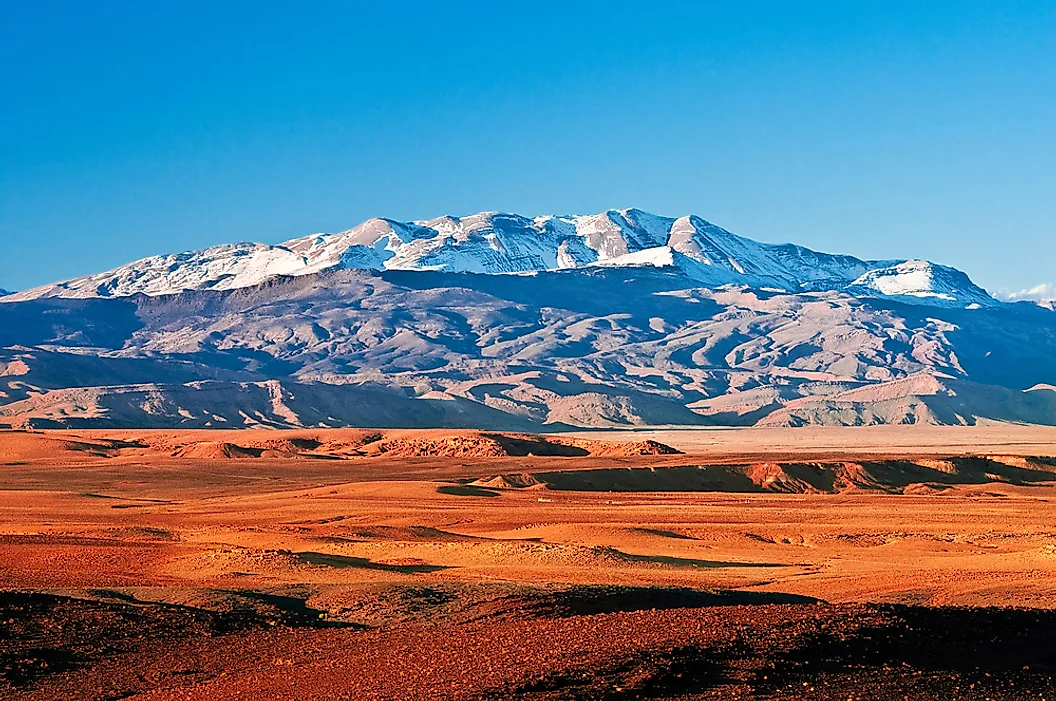
It appears to me that if one wants to make progress in mathematics, one should study the masters and not the pupils. - Niels Henrik Abel.
Nothing is better than reading and gaining more and more knowledge - Stephen William Hawking.
Offline
#2671 2026-01-12 18:11:44
- Jai Ganesh
- Administrator
- Registered: 2005-06-28
- Posts: 53,831
Re: Miscellany
2471) Turkey
Gist
Turkey's landmass covers around 783,000 square kilometers (302,000 square miles). Out of this, about 97% lies in Asia, in the region known as Anatolia or Asia Minor. The remaining 3% lies in Europe, in a region called Eastern Thrace (also known as Turkish Thrace).
Turkey has an emerging free-market economy. It ranked as the 16th-largest in the world and 7th-largest in Europe by nominal GDP in 2025. It also ranked as the 11th-largest in the world and 5th-largest in Europe by PPP in 2025.
Summary
Turkey is a large peninsula that bridges the continents of Europe and Asia.
Turkey is a large peninsula that bridges the continents of Europe and Asia. Turkey is surrounded on three sides by the Black Sea, the Mediterranean Sea, and the Aegean Sea. Istanbul, the largest city in Turkey, is built on land in the Bosporus seaway. The city is partly in Europe and partly in Asia. Turkey is larger than the state of Texas.
Turkey is one of the most earthquake prone areas on Earth and has suffered from 13 earthquakes in the past 70 years. The North Anatolian Fault extends hundreds of miles from the Sea of Marmara in the western part of the country to the Eastern Anatolian Highlands. The fault moves back and forth about 8 inches (20 centimeters) a year.
Turkey's highest mountain, Mount Ararat has two peaks, with Great Ararat reaching 16,945 feet (5,165 meters). The mountain is considered sacred by many people and is believed to be where Noah beached his ark after the great flood.
History
Turkey is home to one of the earliest settlements in the world. Built 8,800 years ago, Catal Hoyuk was a labyrinth of 150 mud homes joined together. There were no streets in between, so people had to enter the homes through holes in the roof!
About 4,000 years ago, the Hittites created an empire in the central part of what is now called Turkey in Anatolia. They ruled for hundreds of years. The Trojan War took place when the Hittites were losing power. The ruins of the city of Troy are believed to be in the city of Hissarlik in Anatolia.
King Midas ruled western Turkey around 700 B.C. In 334 B.C., Alexander the Great took Anatolia under Macedonian Greek rule until Rome took over and Anatolia became part of Roman Asia Minor. In A.D. 330, Constantine became the Roman emperor and formed a new capital called Constantinople. After the fall of the Roman Empire it became part of the Byzantine Empire.
The city of Constantinople was conquered by the Ottomans in 1453 and Turkey became part of the Ottoman Empire. After World War I, the country was invaded by Greece, which led to the Turkish war of Independence in 1920, led by Mustafa Kemal Atatürk. In 1923, the Turkish assembly declared Turkey a republic.
The city formally became Istanbul in 1923. Turkey became a secular country, meaning there is a separation between religion and government. Women gained the right to vote in 1934.
Details
Turkey, officially the Republic of Türkiye, is a country mainly located in Anatolia in West Asia, with a relatively small part called East Thrace in Southeast Europe. It borders the Black Sea to the north; Georgia, Armenia, Azerbaijan, and Iran to the east; Iraq, Syria, and the Mediterranean Sea to the south; and the Aegean Sea, Greece, and Bulgaria to the west. Turkey is home to over 85 million people; most are ethnic Turks, while Kurds are the largest ethnic minority. Officially a secular state, Turkey has a Muslim-majority population. Ankara is Turkey's capital and second-largest city. Istanbul is its largest city and economic center. Other major cities include İzmir, Bursa, and Antalya.
First inhabited by modern humans during the Late Paleolithic, present-day Turkey was home to various ancient peoples. The Hattians were assimilated by the Hittites and other Anatolian peoples. Classical Anatolia transitioned into cultural Hellenization after Alexander the Great's conquests, and later Romanization during the Roman and Byzantine eras. The Seljuk Turks began migrating into Anatolia in the 11th century, starting the Turkification process. The Seljuk Sultanate of Rum ruled Anatolia until the Mongol invasion in 1243, when it disintegrated into Turkish principalities. Beginning in 1299, the Ottomans united the principalities and expanded. Mehmed II conquered Constantinople (modern-day Istanbul) in 1453. During the reigns of Selim I and Suleiman the Magnificent, the Ottoman Empire became a global power. From 1789 onwards, the empire saw major changes, reforms, centralization, and rising nationalism while its territory declined.
In the 19th and early 20th centuries, persecution of Muslims during the Ottoman contraction and in the Russian Empire resulted in large-scale loss of life and mass migration into modern-day Turkey from the Balkans, Caucasus, and Crimea. Under the control of the Three Pashas, the Ottoman Empire entered World War I in 1914, during which the Ottoman government committed genocides against its Armenian, Greek, and Assyrian subjects. Following Ottoman defeat, the Turkish War of Independence resulted in the abolition of the sultanate and the signing of the Treaty of Lausanne. Turkey emerged as a more homogenous nation state. The Republic was proclaimed on 29 October 1923, modelled on the reforms initiated by its founder and first president, Mustafa Kemal Atatürk. Turkey remained neutral during most of World War II, but was involved in the Korean War. Several military interventions interfered with the transition to a multi-party system.
Turkey is an upper-middle-income and emerging country; its economy is the world's 16th-largest by nominal and 11th-largest by PPP-adjusted GDP. As the 15th-largest electricity producer in the world, Turkey aims to become a hub for regional energy transportation. It is a unitary presidential republic. Turkey is a founding member of the OECD, G20, and Organization of Turkic States. With a geopolitically significant location, Turkey is a NATO member and has its second-largest military force. It may be recognized as an emerging, a middle, and a regional power. As an EU candidate, Turkey is part of the EU Customs Union.
Turkey has coastal plains, a high central plateau, and various mountain ranges with rising elevation eastwards. Turkey's climate is diverse, ranging from Mediterranean and other temperate climates to semi-arid and continental types. Home to three biodiversity hotspots, Turkey is prone to frequent earthquakes and is highly vulnerable to climate change. Turkey has a universal healthcare system, growing access to education, and increasing levels of innovativeness. It is a leading TV content exporter. With numerous UNESCO World Heritage sites and intangible cultural heritage inscriptions, and a rich and diverse cuisine, Turkey is the fourth most visited country in the world.
Additional Information
Turkey, also called Türkiye, is a country that occupies a unique geographic position, lying partly in Asia and partly in Europe. Throughout its history it has acted as both a barrier and a bridge between the two continents.
Turkey is situated at the crossroads of the Balkans, Caucasus, Middle East, and eastern Mediterranean. It is among the larger countries of the region in terms of territory and population, and its land area is greater than that of any European state. Nearly all of the country is in Asia, comprising the oblong peninsula of Asia Minor—also known as Anatolia (Anadolu)—and, in the east, part of a mountainous region sometimes known as the Armenian Highland. The remainder—Turkish Thrace (Trakya)—lies in the extreme southeastern part of Europe, a tiny remnant of an empire that once extended over much of the Balkans.
Capital: Ankara
Population: (2024 est.) 86,797,000
Currency Exchange Rate: 1 USD equals 42.685 Turkish lira
The country has a north-south extent that ranges from about 300 to 400 miles (480 to 640 km), and it stretches about 1,000 miles from west to east. Turkey is bounded on the north by the Black Sea, on the northeast by Georgia and Armenia, on the east by Azerbaijan and Iran, on the southeast by Iraq and Syria, on the southwest and west by the Mediterranean Sea and the Aegean Sea, and on the northwest by Greece and Bulgaria. The capital is Ankara, and its largest city and seaport is Istanbul.
Of a total boundary length of some 4,000 miles (6,440 km), about three-fourths is maritime, including coastlines along the Black Sea, the Aegean, and the Mediterranean, as well as the narrows that link the Black and Aegean seas. These narrows—which include the Bosporus, the Sea of Marmara, and the Dardanelles—are known collectively as the Turkish straits; Turkey’s control of the straits, the only outlet from the Black Sea, has been a major factor in its relations with other states. Most of the islands along the Aegean coast are Greek; only the islands of Gökçeada and Bozcaada remain in Turkish hands. The maritime boundary with Greece has been a source of dispute between the two countries on numerous occasions since World War II.
A long succession of political entities existed in Asia Minor over the centuries. Turkmen tribes invaded Anatolia in the 11th century ce, founding the Seljuq empire; during the 14th century the Ottoman Empire began a long expansion, reaching its peak during the 17th century. The modern Turkish republic, founded in 1923 after the collapse of the Ottoman Empire, is a nationalist, secular, parliamentary democracy. After a period of one-party rule under its founder, Mustafa Kemal (Atatürk), and his successor, Turkish governments since the 1950s have been produced by multiparty elections based on universal adult suffrage.
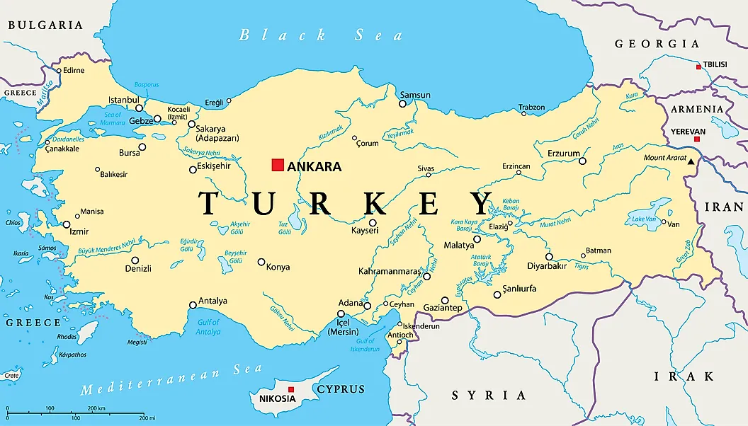
It appears to me that if one wants to make progress in mathematics, one should study the masters and not the pupils. - Niels Henrik Abel.
Nothing is better than reading and gaining more and more knowledge - Stephen William Hawking.
Offline
#2672 2026-01-14 19:55:58
- Jai Ganesh
- Administrator
- Registered: 2005-06-28
- Posts: 53,831
Re: Miscellany
2472) Ulaanbaatar
Gist
Ulaanbaatar (or Ulan Bator) is the capital and largest city of Mongolia, a cultural, industrial, and financial hub located in a valley on the Tuul River. Founded as a nomadic Buddhist center in 1639, it became permanent in 1778 and was renamed Ulaanbaatar ("Red Hero") in 1924, blending Soviet-era buildings with traditional monasteries like Gandan Monastery and a growing modern culture, despite being one of the world's coldest capitals.
The Mongolian capital city of Ulaanbaatar has an average annual temperature of just 28 degrees Fahrenheit — and winter temperatures can reach as low as -40 degrees! The city's geography has much to do with its bone-chilling averages — it's located far inland away from the ocean and at a high altitude of 4,430 feet.
Summary
Ulaanbaatar, capital and largest city of Mongolia. It is situated on the Tuul River on a windswept plateau at an elevation of 4,430 feet (1,350 metres). The city originated as a seasonal migratory abode of the Mongolian princes and in 1639 finally attained permanence on the present site with the construction of Da Khure Monastery. This building became the residence of the bodgo-gegen, high priest of the Tibetan Buddhist religion (to which the Mongols adhere), and remained as such for about 200 years. Da Khure became known to the Russians as Urga and developed as a trade centre between China and Russia. In 1911, when Outer Mongolia declared itself independent, the city was renamed Niislel Khureheh (“Capital of Mongolia”). In 1921 it was occupied by troops of Mongolia’s revolutionary leader, Damdiny Sühbaatar, and the Soviet Red Army. When Mongolia was declared a people’s republic in 1924, the city was renamed Ulaanbaatar, which means “Red Hero.”
With Soviet help, a new city was planned, and its central feature was Sühbaatar Square, site of a Neoclassic government building, a history museum, and the national theatre. The city is also the site of the National University of Mongolia (1942), several professional and technical schools, and the Academy of Sciences of Mongolia.
Ulaanbaatar is the main industrial centre of Mongolia. An industrial complex produces a variety of consumer goods. There are cement, iron, and brick works; footwear and garment factories; vehicle-repair works; food-processing plants; and other factories. A railroad and an international airport connect the city with China and Russia. The scenic wooded peaks of the Hentiyn Mountains extend to the northeast of the city. Pop. (2000) 760,077; (2007 est.) 1,031,200.
Details
Ulaanbaatar is the capital and most populous city of Mongolia. It has a population of 1.67 million, and it is the coldest capital city in the world by average yearly temperature. The municipality is located in north central Mongolia at an elevation of about 1,300 metres (4,300 ft) in a valley on the Tuul River. The city was founded in 1639 as a nomadic Buddhist monastic centre, changing location 29 times, and was permanently settled at its modern location in 1778.
During its early years, as Örgöö (anglicized as Urga), it became Mongolia's preeminent religious centre and seat of the Jebtsundamba Khutuktu, the spiritual head of the Gelug lineage of Tibetan Buddhism in Mongolia. Following the regulation of Qing-Russian trade by the Treaty of Kyakhta in 1727, a caravan route between Beijing and Kyakhta opened up, along which the city was eventually settled. With the collapse of the Qing dynasty in 1911, the city was a focal point for independence efforts, leading to the proclamation of the Bogd Khanate in 1911 led by the 8th Jebtsundamba Khutuktu, or Bogd Khan, and again during the communist revolution of 1921. With the proclamation of the Mongolian People's Republic in 1924, the city was officially renamed Ulaanbaatar and declared the country's capital.
Modern urban planning began in the 1950s, with most of the old ger districts replaced by Soviet-style flats. In 1990, Ulaanbaatar was the site of large demonstrations that led to Mongolia's transition to democracy and a market economy. Since 1990, an influx of migrants from the rest of the country has led to an explosive growth in its population, a major portion of whom live in ger districts, which has contributed to harmful air pollution in winter. Excessive coal production and consumption in Ulaanbaatar make it one of the world's most polluted cities, causing the incidence of pneumonia and other respiratory illnesses to spike amongst children.
Governed as an independent municipality, Ulaanbaatar is surrounded by Töv Province, whose capital Zuunmod lies 43 kilometres (27 mi) south of the city. With a population of just over 1.6 million as of December 2022, it contains almost half of the country's total population. As the country's primate city, it serves as its cultural, industrial and financial heart and the centre of its transport network.
Additional Information
Ulaanbaatar, or Ulan Bator, is the capital and largest city of Mongolia. The city is an independent municipality not part of any provinces. About half the population of Mongolia, about 1.5 million people, live in the city.
Located in the north central part of the country, the city is at an elevation of about 1310 m in a valley on the Tuul River. The city is the country's center for culture, industry and finance, and since it is more than 13 times bigger than the second largest city in Mongolia, Erdenet, it is the country's primate city. Ulaanbaatar is connected by highway to all the major towns in Mongolia and by rail to the Trans-Siberian Railway and Chinese railroad network. The city was founded in 1639 as a Buddhist monastery center and, in the 20th century, grew into a major manufacturing center.
Names
Ulaanbaatar has had many names in its history. From 1639 to 1706, it was known as Örgöö, and from 1706 to 1911 as Ikh Khüree, Da Khüree or simply Khüree. Upon independence in 1911,the city's name changed to Niislel Khüree. When the city became the capital of the new Mongolian People's Republic in 1924, its name was changed to Ulaanbaatar, literally "red hero", in honour of Mongolia's national hero Damdin Sükhbaatar, that liberated Mongolia from Ungern von Sternberg's troops and Chinese occupation with the Soviet Red Army. In Europe and North America, Ulaanbaatar was generally known as Urga (from Örgöö) or sometimes Kuren (from Khüree) or Kulun before 1924.
Geography
Ulaanbaatar is at about 1350 meters (4430 ft) above sea level. For this high elevation, and for the high latitude, and location hundreds of kilometres from any coast, Ulaanbaatar is the coldest national capital in the world, with a subarctic climate.
Symbols
The official symbol of Ulaanbaatar is the garuḍa, a mythical bird in both Buddhist and Hindu mythology called Khan Garuda or Khangar'd by Mongols.
Flag
The city’s flag is sky blue with the garuḍa arms in the center.

It appears to me that if one wants to make progress in mathematics, one should study the masters and not the pupils. - Niels Henrik Abel.
Nothing is better than reading and gaining more and more knowledge - Stephen William Hawking.
Offline
#2673 2026-01-16 19:18:46
- Jai Ganesh
- Administrator
- Registered: 2005-06-28
- Posts: 53,831
Re: Miscellany
2473) Rocky Mountains
Gist
The Rocky Mountains, or Rockies, are a vast mountain system in western North America, stretching over 3,000 miles from British Columbia, Canada, down to New Mexico, USA, forming the Continental Divide and North America's backbone. Known for their dramatic scenery, high peaks (like Colorado's Mount Elbert, the highest), diverse ecosystems, and significant water resources, they influence regional climates, support abundant wildlife, and offer vast recreational opportunities, impacting the culture and economy of both the U.S. and Canada.
The Rocky Mountains, or Rockies, are a vast North American mountain system stretching over 3,000 miles (4,800 km) from northern British Columbia in Canada down through the western United States to New Mexico, forming the continent's spine and influencing climate and river systems. They are a major geographical feature, known for diverse ecosystems, abundant wildlife, and iconic national parks like Rocky Mountain National Park in Colorado.
Summary
The Rocky Mountains, also known as the Rockies, are the largest mountain system in North America, composed of numerous mountain ranges. The Rocky Mountains stretch 3,000 mi (4,800 km)in a straight-line distance from the northernmost part of Western Canada, to New Mexico in the Southwestern United States. Depending on differing definitions between Canada and the U.S., its northern terminus is located either in northern British Columbia's Terminal Range south of the Liard River and east of the Trench, or in the northeastern foothills of the Brooks Range/British Mountains that face the Beaufort Sea coasts between the Canning River and the Firth River across the Alaska–Yukon border. Its southernmost point is near the Albuquerque metropolitan area, adjacent to the Rio Grande rift, and north of the Sandia–Manzano Mountain Range, also near Santa Fe, New Mexico. Being the easternmost portion of the North American Cordillera, the Rockies are distinct from the tectonically younger Cascade Range and Sierra Nevada, which both lie farther to its west.
The Rockies formed 55 million to 80 million years ago during the Laramide orogeny, in which a number of plates began sliding underneath the North American plate. The angle of subduction was shallow, resulting in a broad belt of mountains running down western North America. Since then, further tectonic activity and erosion by glaciers have sculpted the Rockies into dramatic peaks and valleys. At the end of the last ice age, humans began inhabiting the mountain range. After explorations of the range by Europeans, such as Sir Alexander Mackenzie, and Anglo-Americans, such as the Lewis and Clark Expedition, natural resources such as minerals and fur drove the initial economic exploitation of the mountains, although the range itself has never experienced a dense population.
Most of the highest summits of the Rocky Mountains are in Colorado, with the state having an average elevation of 6,800 feet (2,100 m). Public parks and forest lands protect much of the mountain range, and they are popular tourist destinations, especially for hiking, camping, mountaineering, fishing, hunting, mountain biking, snowmobiling, skiing, and snowboarding.
Details
Rocky Mountains is a mountain range forming the cordilleran backbone of the great upland system that dominates the western North American continent. Generally, the ranges included in the Rockies stretch from northern Alberta and British Columbia southward to New Mexico, a distance of some 3,000 miles (4,800 km). In places the system is 300 or more miles wide. Limits are mostly arbitrary, especially in the far northwest, where mountain systems such as the Brooks Range of Alaska are sometimes included. The Rockies are bordered on the east by the Great Plains and on the west by the Interior Plateau and Coast Mountains of Canada and the Columbia Plateau and Basin and Range Province of the United States.
The Rocky Mountains include at least 100 separate ranges, which are generally divided into four broad groupings: the Canadian Rockies and Northern Rockies of Montana and northeastern Idaho; the Middle Rockies of Wyoming, Utah, and southeastern Idaho; the Southern Rockies, mainly in Colorado and New Mexico; and the Colorado Plateau in the Four Corners region of Utah, Colorado, New Mexico, and Arizona. These four subdivisions differ from each other in terms of geology (origin, ages, and types of rocks) and physiography (landforms, drainage, and soils), yet they share the physical attributes of high elevations (many peaks exceeding 13,000 feet [4,000 metres]), great local relief (typically 5,000 to 7,000 feet in vertical difference between the base and summit of ranges), shallow soils, considerable mineral wealth, spectacular scenery from past glaciation and volcanic activity, and common trends in climate, biogeography, culture, economy, and exploration.
Physical features:
Physiography
The Canadian Rockies include the Mackenzie and Selwyn mountains of the Yukon and Northwest Territories (sometimes called the Arctic Rockies) and the ranges of western Alberta and eastern British Columbia. The Northern Rockies include the Lewis and Bitterroot ranges of western Montana and northeastern Idaho. These ranges formed along the eastern edge of a region of carbonate sedimentation some 17 miles (27 km) thick, which had accumulated from the late Precambrian to early Mesozoic time (i.e., between about 1 billion and 190 million years ago). This structural depression, known as the Rocky Mountain Geosyncline, eventually extended from Alaska to the Gulf of Mexico and became a continuous seaway during the Cretaceous Period (about 145 to 66 million years ago). The ranges of the Canadian and Northern Rockies were created when thick sheets of Paleozoic limestones were thrust eastward over Mesozoic rocks during the mountain-building episode called the Laramide Orogeny (65 to 35 million years ago). Some of these thrust sheets have moved 20 to 30 miles (32 to 48 km) to their present positions. The western margin of the Canadian Rockies and Northern Rockies is marked by the Rocky Mountain Trench, a graben (downfaulted, straight, flat-bottomed valley) up to 3,000 feet (900 metres) deep and several miles wide that has been glaciated and partially filled with deposits from glacial meltwaters.
The Columbia Icefield is situated on the continental divide in the Canadian Rockies at elevations of 10,000 to 13,000 feet (3,000 to 4,000 metres) above sea level. It includes the large Athabasca Glacier, which is nearly five miles long and about a mile wide. Glaciers in this ice field, while continuing to move, are thinning and retreating. The Canadian Rockies are about equally divided between drainage to the east (Atlantic and Arctic oceans) and west (Pacific Ocean).
The Middle Rockies include the Bighorn and Wind River ranges in Wyoming, the Wasatch Range of southeastern Idaho and northern Utah, and the Uinta Mountains of northeastern Utah; the Absaroka Range, extending from northwestern Wyoming into Montana, serves as a link between the Northern and Middle Rockies. While the massive deposition of carbonates was occurring in the Canadian and Northern Rockies from the late Precambrian to the early Mesozoic, a considerably smaller quantity of clastic sediments was accumulating in the Middle Rockies. Mountain building there resulted from compressional folding and high-angle faulting, except for the low-angle thrust-faulting in southwestern Wyoming and southeastern Idaho. The granitic core of the anticlinal mountains often has been upfaulted, and many ranges are flanked by Paleozoic sedimentary rocks (e.g., shales, siltstones, and sandstones) that have been eroded into hogback ridges. This same mountain-building process is occurring today in the Andes Mountains of South America. Most mountain building in the Middle Rockies occurred during the Laramide Orogeny, but the mountains of the spectacular Teton Range attained their height less than 10 million years ago by moving more than 20,000 vertical feet relative to the floor of Jackson Hole along an east-dipping fault.
The Bighorn, Wind River, and Uinta ranges all form sharp ridge lines that rise above surrounding basins. The Wind River Range supports a large area of glaciers, including Dinwoody Glacier. These glaciers, however, are retreating fairly rapidly.
Geologic events in the Middle Rockies strongly influenced the direction of stream courses. A special feature of the past 10 million years was the creation of rivers that flowed from basin floors into canyons across adjacent mountains and onto the adjacent plains. This phenomenon resulted from superposition of the streams. The stream courses were initially established in the late Miocene Epoch (about 11.6 to 5.3 million years ago), when the basins were largely filled by deposits of Neogene and Paleogene age (i.e., about 2.6 to 66 million years old) that locally extended across lower segments of mountain axes. During the subsequent regional excavation of the basin fills—which began about five million years ago—the streams maintained their courses across the mountains and cut deep, transverse canyons.
The Yellowstone-Absaroka region of northwestern Wyoming is a distinctive subdivision of the Middle Rockies. A large magma chamber beneath the area has filled several times and caused the surface to bulge, only to then empty in a series of volcanic eruptions of basaltic and rhyolitic lava and ash. Three such cycles have occurred in the past two million years, the most recent of which occurred about 600,000 years ago. The magma chamber is currently filling again, and the land surface in Yellowstone is rising or tilting a slight amount each year.
The Southern Rockies include the Front Range and the Wet and Sangre de Cristo mountains along the eastern slope and the Park, Gore, and Sawatch ranges and the San Juan Mountains along the western slope. The eastern and western ranges are separated by a series of high basins: from north to south they are North Park, the Arkansas River valley, and the San Luis Valley. The Southern Rockies extend northward into southern Wyoming in three prongs: the Laramie and Medicine Bow mountains and the Sierra Madre.
Only about 5,000 feet of sediment accumulated during middle Mesozoic times (about 200 to 150 million years ago) in the region now occupied by the Southern Rockies. Mountain building in these ranges resulted from compressional folding and high-angle faulting during the Laramide Orogeny, as the Mesozoic sedimentary rocks were arched upward over a massive batholith of crystalline rock. Some 10,000 vertical feet of the sedimentary rocks were then eroded; otherwise the Front Range would be approximately twice its present height. The Southern Rockies experienced less of the low-angle thrust-faulting that characterizes the Canadian and Northern Rockies and the western portions of the Middle Rockies.
The ranges of the Southern Rockies are higher than those of the Middle or Northern Rockies, with many peaks exceeding elevations of 14,000 feet. Colorado has 53 peaks over this elevation, the highest being Mount Elbert in the Sawatch Range, which at 14,433 feet (4,399 metres) is the highest point in the Rockies. These ranges were heavily eroded by several episodes of glaciation—the most recent ended about 7,500 years ago, and no active glaciers remain—resulting in spectacular alpine scenery. River valleys have been deepened in the past two million years, first from the direct action of glacier ice and subsequently by glacial meltwaters. Looping, knife-edged moraines occur in most valleys, marking the downslope extent of past glaciations.
The physiographic province called the Colorado Plateau in southeastern Utah, southwestern Colorado, northern Arizona, and northwestern New Mexico is another high-elevation region of the western United States, although it lacks the history of folding, faulting, and volcanic activity of adjacent regions. The uplifts in the Colorado Plateau are not as great as those elsewhere in the Rockies, and therefore less erosion has occurred; Precambrian rocks have been exposed only in the deepest canyons, such as the Grand Canyon.
The plateau is actually a series of plateaus at different elevations arranged in a stairstep sequence through faulting. The horizontal sedimentary rocks have been dissected by the Green and Colorado rivers and their tributaries into a network of deep canyons. Some of these canyons are deeply entrenched meanders, such as the dramatic Goosenecks section of the San Juan River near Mexican Hat, Utah, where erosion through the canyon walls separating opposite sides of a meandering river loop has created a natural bridge.
The Grand Canyon of the Colorado River cuts across the southern end of the Kaibab Upwarp in the southern plateau region. The canyon is up to 6,600 feet (2,000 metres) deep and exposes a remarkable sequence of sedimentary rocks. Weak rock types, such as shale and softer sandstone layers, form low-sloping benches, while more resistant rock types, such as limestone and harder sandstone layers, comprise cliff-forming units. Because of the alternating sequence of weak and resistant rocks in the canyon walls, a cliff-and-bench topography has formed that is typical of much of the Colorado Plateau region. The headward erosion of streams into the plateau surface eventually isolates sections of the plateau into mesas, buttes, monuments, and spires. Bedrock that has been fractured into series of parallel joints can weather into high rock walls known as fins. Subsequent weathering leads to the creation of natural arches. The same weathering processes on cliffs can create niches, which have been exploited by cliff-dwelling Native American cultures in the past.
Four mountain groups—the La Sal, Henry, Abajo, and Carrizo—are notable. From a central pipelike intrusion reaching deep into Earth’s crust, magma has been injected between layers of sedimentary rock, causing the overlying beds to bulge up in domes about one mile across. These domes are called laccoliths, and each of these mountain massifs is made up of a group of laccoliths.
Soils of the Rocky Mountains
Mountain soils in the Rockies are poorly developed, being extremely thin and young and too deficient in nutrients for most types of agriculture. High-valley soils are sometimes suitable for irrigation, depending on texture, steepness of slopes, length of snow cover, and the presence of trace elements (e.g., selenium) that limit suitability for crop cultivation. Rangeland grazing is a more common pursuit. Soils of the Colorado Plateau also are generally shallow and stony, and they contain a high percentage of salts. In some locales, they can be made fertile if sufficient water is available to flush excess salts.
Climate
Along the great north-south extent of the mountains, the climate of the Rockies extends from the northern fringe of the subtropical zone in the far south to the Arctic in the far north. In the south, however, the continentality and high elevation of the mountains tend to reduce the impact of latitude. Two vertical zones prevail throughout much of the range. The lower is characterized as cool temperate, with cold winters and relatively cool summers. This zone occurs between elevations of 7,000 (2,100 metres) and 10,000 feet (3,000 metres) in the south, with upper and lower limits decreasing proportionally with increasing latitude. The higher zone is alpine and tundralike in character, with severe winter conditions and short, cold summers; in the south the highest peaks may remain snow-covered until August, while in the north many of the high valleys sustain permanent glaciers.
Precipitation generally increases from south to north, with the north receiving about three times that of the south. In the south the climate tends to be dry, especially in the rain-shadow valleys. The San Luis Valley in Colorado, for example, has a mountain-desert climate and is one of the driest areas of the Rockies. Much of the total annual precipitation in the south falls as snow in winter, although characteristic of the summer are local, sometimes violent, afternoon thunderstorms. The Northern Rockies tend to receive precipitation more evenly throughout the year from Pacific cyclonic storms. Almost everywhere in the Rockies the growing season is short; some places are susceptible to frosts even in summer.
Plant life
The plant communities of the Rockies vary markedly according to elevation, latitude, and exposure. On the eastern slopes in Colorado and New Mexico, strong winter winds off the arid plains stunt and deform the scattered cedars and piñon pines. The lower elevations at this end of the system are predominantly treeless, except along watercourses, where cottonwoods and other broad-leaved, deciduous species cluster. Sagebrush occurs in valleys and basins as far north as southern Alberta.
Trees of the middle-elevation montane forest include aspen, yellow pine, piñon pine, and Douglas fir. The subalpine forests comprise western hemlock, lodgepole pine, western red cedar, white spruce, and Engelmann spruce. The tree-line elevation descends as latitude increases, and alpine tundra, characterized by low flowering plants, spans nearly the full length of the range. So-called elfin woodland, consisting primarily of dwarfed willows, occurs in the most northerly mountains. The myriad wildflowers of the forests and high meadows include columbine, bunchberry, larkspur, gentian, and Indian paintbrush.
Animal life
The fauna of the Rockies is varied and abundant. Among the large mammals emblematic of the rugged backcountry are the black bear, grizzly bear, mountain lion, and wolverine. Bighorn sheep and mountain goats inhabit the high crags in summer and migrate to the lower slopes for the winter months. Members of the deer family, such as the caribou, elk (wapiti), mule deer, and white-tailed deer, also migrate vertically between alpine meadows and subalpine forest cover; the solitary moose frequents northern lakes, streams, and marshy areas, feeding on willow foliage and aquatic plants. Yellowstone National Park in Wyoming is home to one of the largest herds of bison in North America. Wild horses and burros inhabit the surrounding plains, while coyotes roam the lower valleys and along roads and rail routes. Wolves, brought to near extinction by human predation, remain rare but have resurged since 1970 as their importance in the wilderness ecosystem has come to be appreciated. Smaller mammals of the lower elevations include the least chipmunk, red squirrel, Columbian ground squirrel, black-footed ferret, and marmot. The pika dwells on talus slopes, and the prairie dog inhabits the drier valleys and plateaus. Wildlife of the arid southern mountains comprises the pronghorn, jackrabbit, peccary, rattlesnake, and other desert species. Beavers and river otters can be found in watercourses throughout the region. Amphibians include several species of frogs, toads, and salamanders that are indigenous to the region.
Birdlife is comparably diverse. In summer such raptors as the bald eagle, golden eagle, osprey, peregrine falcon, and turkey vulture nest throughout the range. Several owl species are found, including the great horned owl. Woodland and meadow birds include species of grouse (ruffed, sage, spruce, and blue), ptarmigan, wild turkey, ring-necked pheasant, Clark’s nutcracker, gray jay, and Steller’s jay. Among wading birds are species of egret, crane, great blue heron, curlew, and avocet. An abundance of waterfowl—such as teal, snipe, numerous duck species, and the endangered trumpeter swan—spend the warm season on mountain lakes. Canada geese and white pelicans also spend a portion of the year in the region. The numerous hot springs of the Rockies provide a winter haven for many birds that would otherwise migrate southward.
The rainbow trout, while perhaps the most celebrated fish of the region, is largely introduced from California. The arctic grayling is a prominent denizen of high northern lakes.
The people of the Rocky Mountains
The human presence in the Rocky Mountains has been dated to between 10,000 and 8,000 bce. American Indian peoples inhabiting the northern mountains in modern times include the Shuswap and Kutenai of British Columbia, the Coeur d’Alene and Nez Percé of Idaho, and the Flathead of Montana. The traditional lands of the Shoshone in Idaho and Wyoming and the Ute in Utah and Colorado extended into the west-central ranges. Southwestern groups include the Hopi and other Pueblo Indians and the Navajo. Nomadic Plains Indians who once ranged into the eastern Rockies included the Blackfoot, the Crow, and the Cheyenne.
Incursions by Europeans began in the Southwest in the 16th century. By the early 19th century, exploration and economic exploitation brought them into contact, and often conflict, with virtually all the indigenous mountain peoples. These encounters, along with shifting food supplies and intertribal territorial wars, generated extensive migration and attrition among some groups. Many Native Americans now live on the reservations established throughout the region. Although settlement is now widespread throughout most of the Rockies, population is concentrated in urban areas generally located at the base of mountains, along railways, or in river valleys.
Additional Information
Also referred to as the “Rockies”, the Rocky Mountains are a significant mountain range that dominates the western part of the North American continent. The Rocky Mountains extend for a distance of about 4,800km and are considered North America’s largest mountain system. The Rocky Mountains are bordered by the Great Plains on the east; and by the Canadian Coast Mountains, the Interior Plateau, the Columbia Plateau, and the Basin and Range Province of the United States on the west.
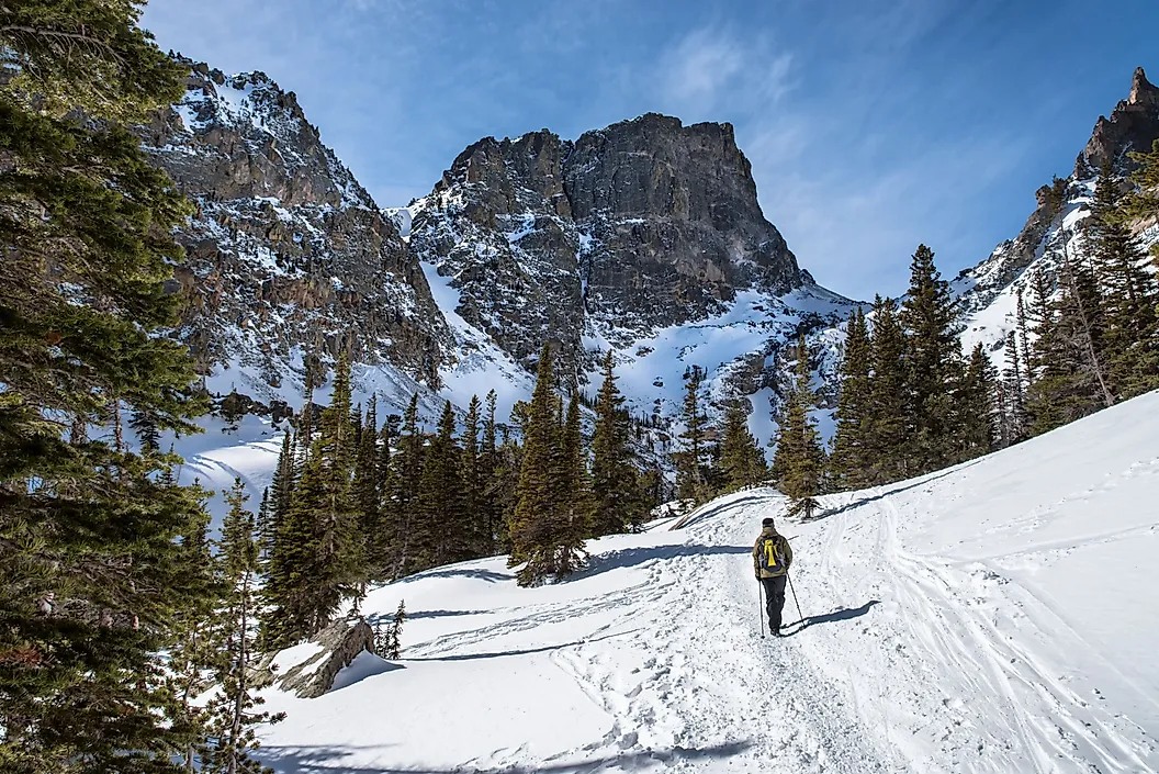
It appears to me that if one wants to make progress in mathematics, one should study the masters and not the pupils. - Niels Henrik Abel.
Nothing is better than reading and gaining more and more knowledge - Stephen William Hawking.
Offline
#2674 2026-01-17 20:47:09
- Jai Ganesh
- Administrator
- Registered: 2005-06-28
- Posts: 53,831
Re: Miscellany
2474) Clavicle
Clavicle
Gist
A clavicle, or collarbone, is a slender, S-shaped bone that connects the breastbone (sternum) to the shoulder blade (scapula), forming part of the shoulder girdle and linking the arm to the body's core. It's the only long bone that lies horizontally, providing stability, protecting nerves and blood vessels, and allowing for a wide range of arm motion, though it's also the body's most commonly fractured bone, often from falls or impacts.
The clavicle (collarbone) is generally considered the weakest bone due to its thin, curved structure and exposed location, making it highly prone to fractures from falls or impacts, while the stapes (stirrup bone) in the middle ear is the smallest and most delicate, though rarely fractured because of its protection. The clavicle's vulnerability comes from its role as a strut connecting the arm to the body, absorbing force, but its slenderness makes it susceptible to snapping.
Summary
Clavicle is the curved anterior bone of the shoulder (pectoral) girdle in vertebrates; it functions as a strut to support the shoulder.
The clavicle is present in mammals with prehensile forelimbs and in bats, and it is absent in sea mammals and those adapted for running. The wishbone, or furcula, of birds is composed of the two fused clavicles; a crescent-shaped clavicle is present under the pectoral fin of some fish. In humans the two clavicles, on either side of the anterior base of the neck, are horizontal, S-curved rods that articulate laterally with the outer end of the shoulder blade (the acromion) to help form the shoulder joint; they articulate medially with the breastbone (sternum). Strong ligaments hold the clavicle in place at either end; the shaft gives attachment to muscles of the shoulder girdle and neck.
The clavicle may be congenitally reduced or absent; its robustness varies with degree of muscle development. The clavicle is a common site of fracture, particularly at the midsection of the bone; horizontal impact to the shoulder, such as from a fall or trauma, is a common cause.
Details
The clavicle, collarbone, or keybone is a slender, S-shaped long bone approximately 15 centimetres (6 in) long that serves as a strut between the shoulder blade and the sternum (breastbone). There are two clavicles, one on each side of the body. The clavicle is the only long bone in the body that lies horizontally. Together with the shoulder blade, it makes up the shoulder girdle. It is a palpable bone and, in people who have less fat in this region, the location of the bone is clearly visible. It receives its name from Latin clavicula 'little key' because the bone rotates along its axis like a key when the shoulder is abducted. The clavicle is the most commonly fractured bone. It can easily be fractured by impacts to the shoulder from the force of falling on outstretched arms or by a direct hit.
Structure
The collarbone is a thin doubly curved long bone that connects the arm to the trunk of the body. Located directly above the first rib, it acts as a strut to keep the scapula in place so that the arm can hang freely. At its rounded medial end (sternal end), it articulates with the manubrium of the sternum (breastbone) at the sternoclavicular joint. At its flattened lateral end (acromial end), it articulates with the acromion, a process of the scapula (shoulder blade), at the acromioclavicular joint.
The rounded medial region (sternal region) of the shaft has a long curve laterally and anteriorly along two-thirds of the entire shaft. The flattened lateral region (acromial region) of the shaft has an even larger posterior curve to articulate with the acromion of the scapula. The medial region is the longest clavicular region as it takes up two-thirds of the entire shaft. The lateral region is both the widest clavicular region and thinnest clavicular region. The lateral end has a rough inferior surface that bears a ridge, the trapezoid line, and a slight rounded projection, the conoid tubercle (above the coracoid process). These surface features are attachment sites for muscles and ligaments of the shoulder.
It can be divided into three parts: medial end, lateral end, and shaft.
Medial end
The medial end is also known as the sternal end. It is quadrangular and articulates with the clavicular notch of the manubrium of the sternum to form the sternoclavicular joint. The articular surface extends to the inferior aspect for articulation with the first costal cartilage.
Lateral end
The lateral end is also known as the acromial end. It is flat from above downward. It bears a facet that articulates with the shoulder to form the acromioclavicular joint. The area surrounding the joint gives an attachment to the joint capsule. The anterior border is concave forward and the posterior border is convex backward.
Shaft
The shaft is divided into two main regions, the medial region, and the lateral region. The medial region is also known as the sternal region, it is the longest clavicular region as it takes up two-thirds of the entire shaft. The lateral region is also known as the acromial region, it is both the widest clavicular region and thinnest clavicular region.
Lateral region of the shaft
The lateral region of the shaft has two borders and two surfaces.
* the anterior border is concave forward and gives origin to the deltoid muscle.
* the posterior border is convex and gives attachment to the trapezius muscle.
* the inferior surface has a ridge called the trapezoid line and a tubercle; the conoid tubercle for attachment with the trapezoid and the conoid ligament, part of the coracoclavicular ligament that serves to connect the collarbone with the coracoid process of the scapula.
Development
The collarbone is the first bone to begin the process of ossification (laying down of minerals onto a preformed matrix) during development of the embryo, during the fifth and sixth weeks of gestation. However, it is one of the last bones to finish ossification at about 21–25 years of age. Its lateral end is formed by intramembranous ossification while medially it is formed by endochondral ossification. It consists of a mass of cancellous bone surrounded by a compact bone shell. The cancellous bone forms via two ossification centres, one medial and one lateral, which fuse later on. The compact forms as the layer of fascia covering the bone stimulate the ossification of adjacent tissue. The resulting compact bone is known as a periosteal collar.
The collarbone has a medullary cavity (marrow cavity) in its medial two-thirds. It is made up of spongy cancellous bone with a shell of compact bone. It is a dermal bone derived from elements originally attached to the skull.
Variation
The shape of the clavicle varies more than most other long bones. It is occasionally pierced by a branch of the supraclavicular nerve. In males the clavicle is usually longer and larger than in females. A study measuring 748 males and 252 females saw a difference in collarbone length between age groups 18–20 and 21–25 of about 6 and 5 mm (0.24 and 0.20 in) for males and females respectively.
The left clavicle is usually longer and weaker than the right clavicle.
The collarbones are sometimes partly or completely absent in cleidocranial dysostosis.
The levator claviculae muscle, present in 2–3% of people, originates on the transverse processes of the upper cervical vertebrae and is inserted in the lateral half of the clavicle.
Additional Information
Your clavicle (collarbone) is a part of your skeletal system that connects your arm to your body. Ligaments connect this long, thin bone to your sternum and shoulder. Your clavicle is prone to injuries like a clavicle fracture, dislocated shoulder and separated shoulder. Falls are a top cause of clavicle injuries.
Overview:
What is a clavicle?
Your clavicle (collarbone) is a long, slightly curved bone that connects your arm to your body. You’ll find one on both sides of the base of your neck. The bones help keep your shoulder blade in the correct position as you move.
The word “clavicle” comes from the Latin “clavicula,” which translates to “little key.” The bone is actually shaped a bit like an old-fashioned key. And it works in much the same way. When you rotate a key, it moves the lock. Similarly, when you lift your arm, your clavicle rotates along its axis to allow movement.
Because of its location and role in shoulder movement, your clavicle bone is prone to injury. These injuries are common in contact sports, falls (especially when you put your arm out to catch yourself) and trauma like car accidents. Sometimes, babies can get a clavicle injury during birth.
What are clavicles made of?
Your clavicles are bones, and bones are made of layers of cells and proteins. They have a hard outer layer or shell, and an inner layer of spongy bone (cancellous bone) tissue.
What is its purpose?
Your clavicles are long bones that support your upper body and play an important role in how you move. They hold your shoulder in place, allowing you to transfer weight from your upper body to your head, neck, back and chest (your axial skeleton).
Anatomy:
Where is the clavicle located?
In an adult, each clavicle is about 6 inches long and runs along the top of your chest at the front of your shoulder. It runs horizontally (from side to side). Strong bands of tissue (ligaments) connect your sternum (breast bone) in the middle of your ribcage to your shoulder blade (scapula).
Conditions and Disorders:
What are the common conditions and disorders that affect the clavicle?
Your clavicle is long and narrow. It lies right under the surface of your skin, making it prone to fractures and injuries. Active children, teens and those who play contact sports are more prone to injuries like dislocated shoulders. Adults, especially those who are older, are more prone to falls that cause broken clavicles.
Types of clavicle injuries include:
* Clavicle fracture. Your clavicle bone breaks in one place or several places (comminuted fracture). A healthcare provider calls it a displaced clavicle fracture when the ends of the broken bones don’t line up.
* Separated shoulder. You tear the ligament connecting your clavicle and shoulder blade, and they separate. A shoulder separation can put your clavicle out of alignment. It causes pain and a bump underneath your skin.
Other conditions that can affect your clavicle include:
* Osteoarthritis.
* Bone cancer.
* Osteomyelitis.
* Thoracic outlet syndrome.
Common symptoms of clavicle conditions
Pain is the most common symptom of clavicle conditions. Other symptoms include:
* Swelling.
* Inability to lift your arm or grasp items.
* Bruising or discoloration.
* A lump or bump near your clavicle.
If you think you’ve broken your clavicle, go to the emergency room (ER). A healthcare provider should diagnose and treat a clavicle fracture as soon as possible to make sure it heals correctly.
How common are clavicle injuries?
A broken clavicle is a common injury in adults. It accounts for about 5% of (1 in 20) adult fractures.
Common tests to check for clavicle conditions
If you have symptoms of a clavicle injury or another clavicle condition, a healthcare provider might suggest one or more of the following imaging tests:
* X-ray.
* Magnetic resonance imaging (MRI).
* A computed tomography (CT) scan.
Common treatments for the clavicle
Treatment for clavicle pain or injury depends on what sort of problem you’re having. It might include:
* Resting or immobilizing your shoulder to allow the bone to heal. Your healthcare provider might give you a sling.
* Ice packs for 20 minutes at a time.
* Over-the-counter (OTC) pain relievers like aspirin, ibuprofen or acetaminophen.
If you’ve fractured your clavicle, you might need surgery to get your bones back where they belong and secure them in place.
Care:
How can I protect my clavicle?
These steps can keep your clavicle and the rest of your skeletal system healthy and strong:
* Do weight-bearing exercises like walking, jogging or tennis for at least 30 minutes most days of the week.
* Get enough vitamin D and calcium in your diet to build strong bones.
* Lift weights or do other resistance exercises to strengthen bones.
* Prevent falls by being cautious on stairs and removing tripping hazards.
* Quit smoking and cut back on alcohol.
* Wear protective gear when participating in contact sports (shoulder pads) and physical activities like biking (helmet).

It appears to me that if one wants to make progress in mathematics, one should study the masters and not the pupils. - Niels Henrik Abel.
Nothing is better than reading and gaining more and more knowledge - Stephen William Hawking.
Offline
#2675 2026-01-19 19:01:16
- Jai Ganesh
- Administrator
- Registered: 2005-06-28
- Posts: 53,831
Re: Miscellany
2475) North Pole
North Pole
Gist
The Geographic North Pole isn't in any country because it sits in the middle of the Arctic Ocean, a region of international waters covered by shifting sea ice, not land. While Canada, Russia, the U.S. (Alaska), Norway, and Denmark (Greenland) border the Arctic Circle, they don't claim the Pole itself, though there are overlapping territorial claims over the ocean floor and resources.
Can humans visit the North Pole?
Yes, it is possible to reach the Geographic North Pole. However, the options are very limited for getting to this incredibly remote place: On foot: Hardy modern-day explorers test themselves by skiing and man hauling their own sled over the ice for many weeks.
Which city is closest to North Pole?
Longyearbyen is located at latitude 78˚ North – just 1,316 km from the North Pole. Longyearbyen is a three-hour flight from Oslo or a 90-minute flight from Tromsø.
Summary
North Pole, the northern end of Earth’s axis, lying in the Arctic Ocean, about 450 miles (725 km) north of Greenland. This geographic North Pole does not coincide with the magnetic North Pole—to which magnetic compasses point and which in the early 21st century lay north of the Queen Elizabeth Islands of extreme northern Canada at approximately 82°15′ N 112°30′ W (it is steadily migrating northwest)—or with the geomagnetic North Pole, the northern end of Earth’s geomagnetic field (about 79°30′ N 71°30′ W). The geographic pole, located at a point where the ocean depth is about 13,400 feet (4,080 metres) deep and covered with drifting pack ice, experiences six months of complete sunlight and six months of total darkness each year.
The American explorer Robert E. Peary claimed to have reached the pole by dog sledge in April 1909, and another American explorer, Richard E. Byrd, claimed to have reached it by airplane on May 9, 1926; the claims of both men were later questioned. Three days after Byrd’s attempt, on May 12, the pole was definitely reached by an international team of Roald Amundsen, Lincoln Ellsworth, and Umberto Nobile, who traversed the polar region in a dirigible.
The first ships to visit the pole were the U.S. nuclear submarines Nautilus (1958) and Skate (1959), the latter surfacing through the ice, and the Soviet icebreaker Arktika was the first surface ship to reach it (1977). Other notable surface expeditions include the first confirmed to reach the pole (1968; via snowmobile), the first to traverse the polar region (1969; Alaska to Svalbard, via dog sled), and the first to travel to the pole and back without resupply (1986; also via dog sled); the last expedition also included the first woman to reach the pole, American Ann Bancroft. After reaching the South Pole on January 11, 1986, the British explorer Robert Swan led an expedition to the North Pole, reaching his destination on May 14, 1989 and thereby becoming the first person to walk to both poles.
Details
The North Pole, also known as the Geographic North Pole or Terrestrial North Pole, is the point in the Northern Hemisphere where the Earth's axis of rotation meets its surface. It is called the True North Pole to distinguish from the Magnetic North Pole.
The North Pole is by definition the northernmost point on the Earth, lying antipodally to the South Pole. It defines geodetic latitude 90° North, as well as the direction of true north. At the North Pole all directions point south; all lines of longitude converge there, so its longitude can be defined as any degree value. No time zone has been assigned to the North Pole, so any time can be used as the local time. Along tight latitude circles, counterclockwise is east and clockwise is west. The North Pole is at the center of the Northern Hemisphere. The nearest land is usually said to be Kaffeklubben Island, off the northern coast of Greenland about 700 km (430 mi) away, though some perhaps semi-permanent gravel banks lie slightly closer. The nearest permanently inhabited place is Alert on Ellesmere Island, Canada, which is located 817 km (508 mi) from the Pole.
While the South Pole lies on a continental land mass, the North Pole is located in the middle of the Arctic Ocean amid waters that are almost permanently covered with constantly shifting sea ice. The sea depth at the North Pole has been measured at 4,261 m (13,980 ft) by the Russian Mir submersible in 2007 and at 4,087 m (13,409 ft) by USS Nautilus in 1958. This makes it impractical to construct a permanent station at the North Pole (unlike the South Pole). However, the Soviet Union, and later Russia, constructed a number of manned drifting stations on a generally annual basis since 1937, some of which have passed over or very close to the Pole. Since 2002, a group of Russians have also annually established a private base, Barneo, close to the Pole. This operates for a few weeks during early spring. Studies in the 2000s predicted that the North Pole may become seasonally ice-free because of Arctic ice shrinkage, with timescales varying from 2016 to the late 21st century or later.
Attempts to reach the North Pole began in the late 19th century, with the record for "Farthest North" being surpassed on numerous occasions. The first undisputed expedition to reach the North Pole was that of the airship Norge, which overflew the area in 1926 with 16 men on board, including expedition leader Roald Amundsen. Three prior expeditions – led by Frederick Cook (1908, land), Robert Peary (1909, land) and Richard E. Byrd (1926, aerial) – were once also accepted as having reached the Pole. However, in each case later analysis of expedition data has cast doubt upon the accuracy of their claims.
The first verified individuals to reach the North Pole on foot was in 1948 by a 24-man Soviet party, part of Aleksandr Kuznetsov's Sever-2 expedition to the Arctic, who flew near to the Pole first before making the final trek to the Pole on foot. The first complete land expedition to reach the North Pole was in 1968 by Ralph Plaisted, Walt Pederson, Gerry Pitzl and Jean-Luc Bombardier, using snowmobiles and with air support.
Precise definition
The Earth's axis of rotation – and hence the position of the North Pole – was commonly believed to be fixed (relative to the surface of the Earth) until, in the 18th century, the mathematician Leonhard Euler predicted that the axis might "wobble" slightly. Around the beginning of the 20th century astronomers noticed a small apparent "variation of latitude", as determined for a fixed point on Earth from the observation of stars. Part of this variation could be attributed to a wandering of the Pole across the Earth's surface, by a range of a few metres. The wandering has several periodic components and an irregular component. The component with a period of about 435 days is identified with the eight-month wandering predicted by Euler and is now called the Chandler wobble after its discoverer. The exact point of intersection of the Earth's axis and the Earth's surface, at any given moment, is called the "instantaneous pole", but because of the "wobble" this cannot be used as a definition of a fixed North Pole (or South Pole) when metre-scale precision is required.
It is desirable to tie the system of Earth coordinates (latitude, longitude, and elevations or orography) to fixed landforms. However, given plate tectonics and isostasy, there is no system in which all geographic features are fixed. Yet the International Earth Rotation and Reference Systems Service and the International Astronomical Union have defined a framework called the International Terrestrial Reference System.
Additional Information
The North Pole is the northernmost point on Earth. It is the precise point of the intersection of Earth's axis and Earth's surface.
From the North Pole, all directions are south. Its latitude is 90 degrees north, and all lines of longitude meet there (as well as at the South Pole, on the opposite end of Earth). Polaris, the current North Star, sits almost motionless in the sky above the pole, making it an excellent fixed point to use in celestial navigation in the Northern Hemisphere.
The North Pole sits in the middle of the Arctic Ocean, on water that is almost always covered with ice. The ice is about two to three meters (six to 10 feet) thick. The depth of the ocean at the North Pole is more than 4,000 meters (13,123 feet).
The Canadian territory of Nunavut lies closest to the North Pole. Greenland, the world's largest island and an autonomous teterritory within the Kingdom of Denmark, is also close to the pole.
The North Pole is much warmer than the South Pole. This is because sits at a lower elevation (sea level) and is located in the middle of an ocean, which is warmer than the ice-covered continent of Antarctica. But it's not exactly beach weather. In the summer, the warmest time of year, the temperature is right at the freezing point: 0 degrees Celsius (32 degrees Fahrenheit.)
Because Earth rotates on a tilted axis as it revolves around the sun, sunlight is experienced in extremes at the poles. In fact, the North Pole experiences only one sunrise (at the March equinox) and one sunset (at the September equinox) every year. From the North Pole, the sun is always above the horizon in the summer and below the horizon in the winter. This means the region experiences up to 24 hours of sunlight in the summer and 24 hours of darkness in the winter.
Drifting Research Stations
Since the North Pole sits on drifting ice, it's difficult and expensive for scientists and explorers to study. There isn’t land or a place for permanent facilities, making it difficult to set up equipment.
The most consistent research of the North Pole has come from manned drifting research stations. Russia sends out a drifting station almost every year, all named "NP" (for North Pole). Drifting stations monitor the ice pack, temperature, sea depth, currents, weather conditions, and marine biology of the North Pole.
As their name implies, drifting stations move with the drifting ice pack in the Arctic Ocean. They usually last two or three years before before the warmer climate of the Greenland Sea breaks up the ice floe.
North Pole drifting stations are responsible for many discoveries about the ecosystem at the North Pole. In 1948, for example, bathymetry studies revealed the massive Lomonosov Ridge. The Lomonosov Ridge is an underwater mountain chain stretching across the North Pole, from the Siberian region of Russia all the way to Ellesmere Island, Canada.
Drifting stations have recorded the development of cyclones in the Arctic, as well Arctic shrinkage. Arctic shrinkage is climate change in the Arctic, including warming temperatures, the melting of the Greenland ice sheet (resulting in more freshwater in the marine environment), and a loss of sea ice.
Ecosystems at the North Pole
Polar bears (Ursus maritimus), Arctic foxes (Vulpes lagopus), and other terrestrial animals rarely migrate to the North Pole. The drifting ice is an unpredictable habitat, and does not allow for regular migration routes or the establishment of dens in which to raise young. Still, polar bears sometimes wander into the area in search of food.
The undersea ecosystem of the North Pole is more varied than the ice above it. Shrimp, sea anemones, and tiny crustaceans inhabit in the area. A few ringed seals (Pusa hispida) have been spotted. (Ringed seals are common prey of the polar bears that wander into the region.) Larger marine mammals, such as narwhals (Monodon monoceros), are much more rare.
Several species of fish live at the North Pole. Arctic cod are the most abundant. Arctic cod (Boreogadus saida) are small fish usually found near the seafloor, close to their food sources—tiny shrimp and crustaceans.
Birds are frequent visitors to the North Pole. The Arctic tern (Sterna paradisaea), which has the longest annual migration of any species on the planet, spends its spring and summer in the Arctic, though rarely as far north as the North Pole. It then flies 30,000 kilometers (18,641 miles) south, to the Antarctic Circle. The Arctic tern makes an Arctic-Antarctic round-trip migration every year.
Like the Arctic tern, all other birds spotted near the North Pole are migratory. They include the small snow bunting (Plectrophenax nivalis) and gull-like fulmars and kittiwakes.
Exploration
Major polar exploration by non-Indigenous people began in the 19th century. The first expedition specifically to reach the North Pole was led by British Admiral William Edward Parry in 1827. Norwegian explorers Fridtjof Nansen and Hjalmar Johansen attempted a land-based expedition in 1895. A Swedish expedition led by Salomon August Andree tried to fly over the North Pole in a hydrogen balloon two years later.
The first person to claim reaching the North Pole was American explorer Frederick Albert Cook, in 1908. Cook was unable to provide any navigational records of his achievement, however, and rest of his team later reported that they did not quite reach the pole. The claim remains controversial.
A year later, another American explorer, Robert Peary, claimed to reach the North Pole. Peary was supported and funded by the National Geographic Society, which verified his claim. It has been in dispute ever since.
Although Peary's North Pole team included four other people, none of them were trained in navigation. They were therefore unable to verify Peary's claims, and one of them, Matthew Henson, reported a conflicting route from Peary. Peary himself never made his navigational records available for review. Skeptics have noted the remarkable speed with which the expedition traveled once Capt. Bob Bartlett, the only other navigator, left the crew. Peary reported more than doubling the amount of territory covered daily as soon as Bartlett left the expedition.
Nonetheless, many explorers support Peary's claims. National Geographic conducted extensive studies of the photographs Peary took, and concluded they were taken within eight kilometers (five miles) of the pole. (The photographs themselves have never been made public.) Depth soundings taken by Peary and Henson also seem to support their claim to have reached the pole.
Perhaps the most important support for Peary's claim came from British explorer Tom Avery's polar expedition of 2005. Avery mimicked Peary's supposed route, using sled dog teams. The expedition successfully reached the North Pole.
The first verified expedition to the North Pole was conducted by Norwegian explorer Roald Amundsen in 1926. Amundsen did not use a ship or dogsleds—he flew over the pole on the airship Norge. The Norge, lifted by hydrogen and powered by a diesel engine, flew over the North Pole on its route from the Norwegian Arctic to the U.S. state of Alaska.
The first people verified to have set foot at the North Pole were a research group of geologists and oceanographers from the Soviet Union in 1948. The scientists were flown in and out of the pole over a three-day period.
The first watercraft to reach the North Pole was a nuclear-powered submarine, the USS Nautilis, in 1958. Another U.S. submarine, the USS Skate, broke through the sea ice to surface near the North Pole about a year later.
The first verified expeditions to reach the North Pole by foot didn't happen until the late 1960s. A team led by American explorer Ralph Plaisted used snowmobiles to reach the pole in 1968. A year later, an expedition led by British explorer Wally Herbert reached the pole on foot, with the aid of dogsleds and airlifted (flown-in) supplies. In 1986, 77 years after Robert Peary made his claim, a team led by National Geographic Explorer Emeritus Will Steger became the first verified expedition to reach the North Pole by dogsled without resupply.
Shipping through the North Pole
Today, large, powerful ships called icebreakers are often used to navigate the ocean around the North Pole. Icebreakers carve through the sea ice to make way for cargo and military ships.
Icebreakers have very strong steel bows that can break through ice at a rate of about 10-20 knots (19-37 kilometers per hour, or 12-23 miles per hour). Until the 1990s, all icebreakers that traversed the North Pole were nuclear-powered. Arctic shrinking and the reduction of sea ice have since allowed diesel-powered icebreakers to navigate the North Pole.
Fewer icebreakers may be needed in the future. Due to Arctic shrinkage, North Pole may be ice-free in the summer months by 2035.
Cargo ships traveling between Asia, North America, and Europe save money by navigating the so-called Northern Sea Route, a trade route which often includes the North Pole. Ships carrying cargo such as oil, natural gas, minerals, and grain regularly use the Northern Sea Route. This saves companies hundreds of thousands of dollars by avoiding the long trip to and through the Panama Canal.
Resources and Territorial Claims
No one actually lives at the North Pole. Inuit people, who live in the nearby Arctic regions of Canada, Greenland, and Russia, have never made homes at the North Pole. The ice is constantly moving, making it nearly impossible to establish a permanent community.
The Arctic Council, composed of nations with territory in the Arctic Circle, addresses issues faced by nations and indigenous people of the Arctic, including the North Pole. Canada, Denmark, Finland, Iceland, Norway, Russia, Sweden, and the United States are members of the Arctic Council.
The possibility of an ice-free trade route between Europe, North America, and Asia makes the North Pole an economically valuable territory. Oil and gas exploration have proved lucrative in other parts of the Arctic, and the possibility of extractive activity around the North Pole's seabed interests many businesses, scientists, and engineers.
However, taking advantage of sea routes or resources at the North Pole is politically delicate. The North Pole is in the middle of the Arctic Ocean, outside the territorial claims of any nation. However, international laws allowing nations to claim land extending along their continental shelf are currently being explored.
Russia, Canada, Denmark (via its autonomous territory of Greenland), and Norway have all claimed areas extending from their continental shelves, with Canada and Russia voicing the strongest claims.
In 2007, a Russian research expedition using sophisticated submersibles became the first to descend to the actual seabed beneath the North Pole. The expedition, Arktika, planted a titanium Russian flag on the spot.
Other Arctic nations reacted strongly. The United States issued a statement dismissing any Russian claim to the region. Canada's Minister of Foreign Affairs used a line from the Canadian national anthem in a rebuke: "This is the true north strong and free, and they're fooling themselves if they think dropping a flag on the ocean floor is going to change anything."
Russian leaders acknowledged Arktika was an expedition to prepare evidence supporting the North Pole as part of the Lomonosov Ridge—an extension of the continental shelf off Russia. However, expedition leaders questioned other Arctic nations' reaction.
"When pioneers reach a point hitherto unexplored by anybody," the Russian Minister of Foreign Affairs said, "it is customary to leave flags there. Such was the case on the Moon, by the way."
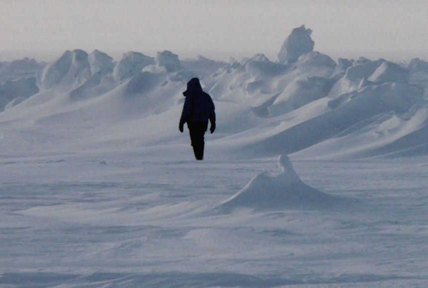
It appears to me that if one wants to make progress in mathematics, one should study the masters and not the pupils. - Niels Henrik Abel.
Nothing is better than reading and gaining more and more knowledge - Stephen William Hawking.
Offline